Joist Designation Examples
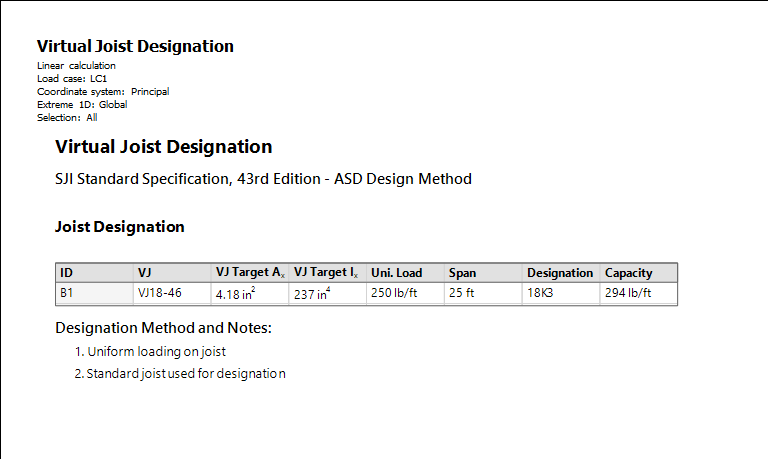
Example 1 - Uniformly loaded Joist
The following joist has a span of 25 feet and an un-factored uniform load of 250 lb/ft. Through auto-design, a virtual joist VJ18-46 was selected to meet the design requirements.
In the Setup, the following settings are used:
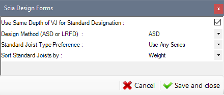
As part of the Summary output of the virtual joist designation component, a standard joist designation of 18K3 is given based on the uniform load and span along with the capacity of the 18K3 at 25 feet.

Example 2 – KCS Joist with Point Load
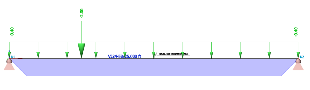
The following joist has a span of 25 feet, an un-factored uniform load of 400 lb/ft and a concentrated load of 2,000 lbs. at 6’-3” from one end of the joist. Through auto design, a virtual joist VJ24-58 was selected to meet the design requirements.
The settings from Example 1 are used in the Setup. (Note that while the standard joist type preference and sorting method can be set in this example, they will not be used since the point load on the joist disqualifies the joist from receiving a standard joist designation).
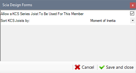
In the 1D Member data, the following settings are used to allow a KCS joist to be selected for the joist and to sort KCS joists by Moment of Inertia.

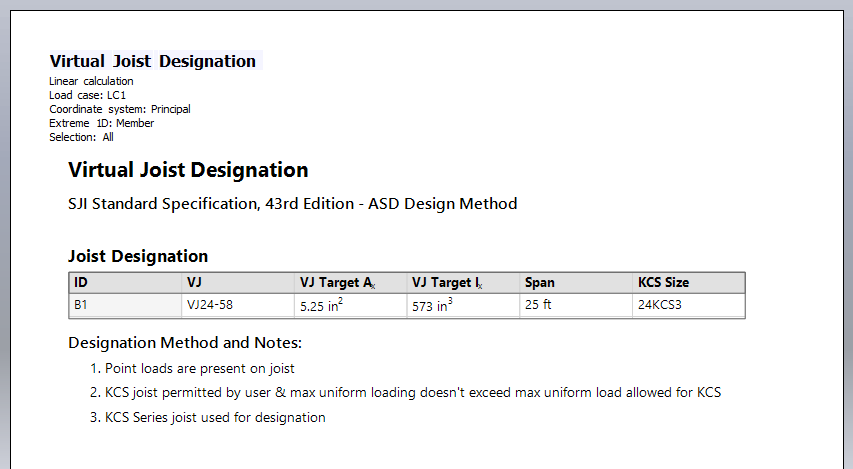
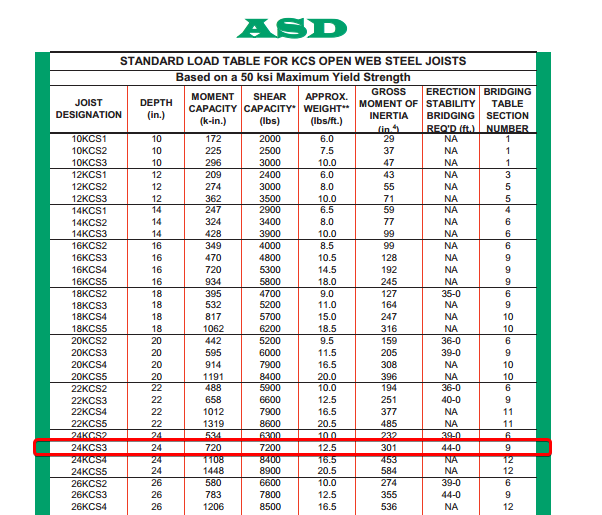
The Summary output of Virtual Joist Designation, shows the virtual joist name (VJ24- 58), the area and moment of inertia of the virtual joist cross-section, as well as a KCS series joist designation which has a shear and moment capacity greater than or equal to the applied shear and moment applied to the joist. The Designation Method and Notes displays the reasoning for using a KCS series joists for this member – that there is a point load on the joist, the user has selected to allow a KCS joist to be used, and the uniform load does not exceed the maximum un-factored uniform load allowed on the KCS joist.
Example 3 – Special Joist with Point Load
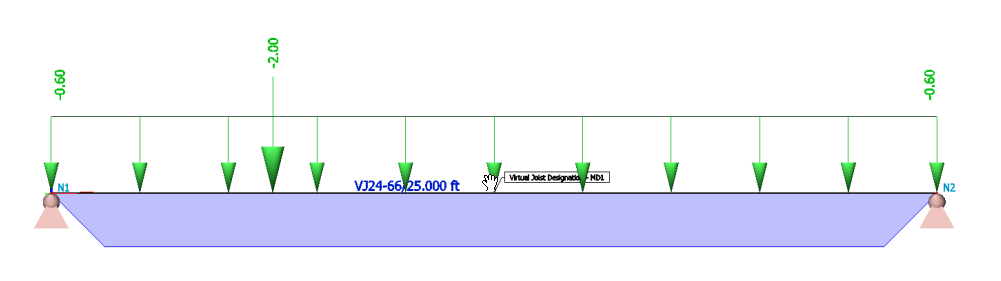
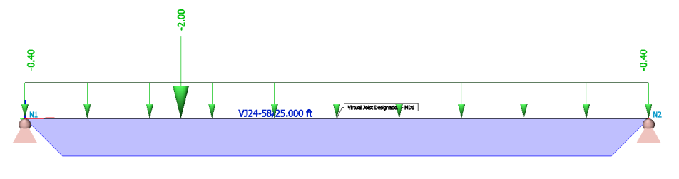
Similar to Example 2, the following joist has a span of 25 feet and a concentrated load of 2,000 lbs. at 6’-3” from one end of the joist. However, this joist has an un-factored uniform load of 600 lb/ft.
The settings from Example 1 and 2 are again used in the Setup.
In the 1D Member data, the following settings are used to allow a KCS joist to be selected for the joist and to sort KCS joists by Moment of Inertia.
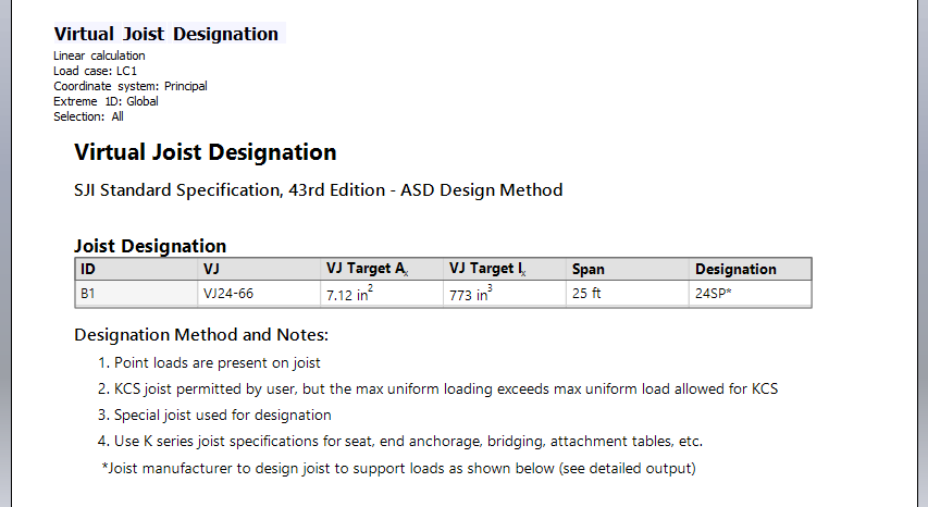
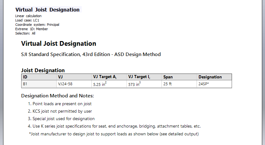
The Summary output of Virtual Joist Designation, displays the virtual joist name (VJ24-66), the area and moment of inertia of the virtual joist cross-section. In this example, the uniform load of 600 lb/ft exceeds the maximum un-factored uniform load allowed on a KCS joist (550 lb/ft). For this reason, a KCS joist cannot be used and the joist will use the “special” designation. The joist is given a special designation of 24SP*. The Designation Method and Notes displays the reasoning for the special designation, the standard series joist which should be used for specifying seat dimensions, end anchorage, bridging, and attachment tables as well as a note to communicate to the joist manufacturer to design the joist according to the loads displayed.
Example 4 – Special Joist with Point Load #2
Special Joist with Point Load #2 Similar to Example 2, the following joist has a span of 25 feet, an un-factored uniform load of 400 lb/ft and a concentrated load of 2,000 lbs. at 6’-3” from one end of the joist. Through auto-design, a virtual joist VJ24-58 was selected to meet the design requirements.
The settings from Examples 1 & 2 are again used in the Setup.
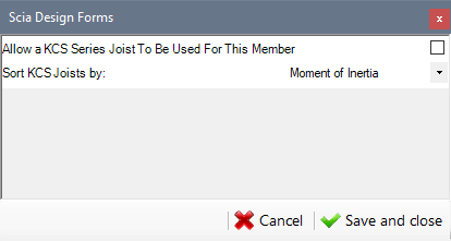
In the 1D Member data, the following settings are used to not allow a KCS joist to be selected for the joist.
Because there is a concentrated load with a magnitude greater than 100 lbs. on this joist and allowing a KCS joist was not selected, this joist receives a special designation. The Summary output of the Virtual Joist Designation displays the virtual joist name (VJ24-58), the area and moment of inertia of the virtual joist crosssection, and the special joist designation (24SP*). As in Example 3, the Designation Method and Notes displays the reasoning for the special designation, the standard series joist which should be used for specifying seat dimensions, end anchorage, bridging, and attachment tables as well as a note to communicate to the joist manufacturer to design the joist according to the loads displayed.
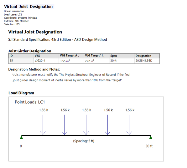
Example 5 - Joist and Joist Girder with Metal Deck
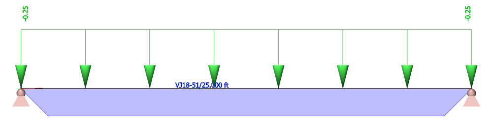
Joist and Joist Girder with Metal Deck In the following example, there are two joist girders, which support five 25 ft long interior infill joists. The infill joists are spaced at 5 ft. apart and support a metal deck which has a dead load of 25 lb/ft2. Through auto-design, the interior infill joists become VJ16-38s and the joist girders become VJ20-1s.
The settings from Examples 1-4 are used in the Setup. 1-D Member Data is not required for the joists or joist girders, since there are not point loads or not-uniform loading on the joists and the joist girders should not receive a KCS Series designation.

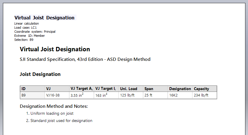
The Summary output is shown for one of the joists and the Detailed output is shown one of the joist girders. For both, the ID of the joist, the cross-section name, area, and moment of inertia are displayed in the table.
For the joist, the uniform load and span are given as well as the standard joist designation and capacity of the standard joist.
For the joist girder, the designation consists of the member’s depth (20 inches), the letter “G” to represent that this member is a girder, the number of spaces between joists (6), and the end reaction forces from the joists (1.56K). In addition, a load diagram illustrating the forces on the joist girder and their spacing is also shown. Note that while there are a total of seven joists on the joist girders, the end reactions forces from the exterior joists (VJ10-27s) are supported directly by the columns, and therefore, the forces are not shown on the load diagram.