Press only
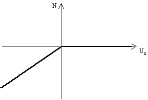
Press-only 1D members (i.e. 1D members not able to bear any tension) show behaviour to the following stress-strain diagram:
When inserted into the model, such a 1D member is marked with the following symbol (remember that in order to see the symbol, view parameters must be adjusted to show model data).
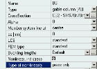
The compression-only property can be adjusted in a property table of a particular beam.
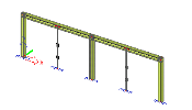
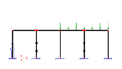
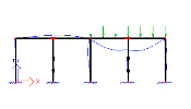
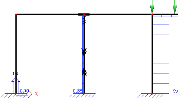
The effect of this option will be shown on the following example. Let’s assume a simple two-span frame whose horizontal beams must be, for some reason or another, supported during the assembly phase by props.
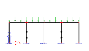
Further, let’s assume that the frame is subject to two load cases during this assembly phase. The first one represents a uniform distributed load acting on both spans.
The other one contains a uniform distributed load on the right hand side span only.
You may have noticed the mark on the props. The pair of double arrows indicates that the beam is of compression-only type.
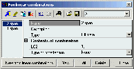
A non-linear calculation can only be performed for a non-linear combination even if the combination should contain just one load case. Therefore, let’s define two non-linear combinations, one for the two-span load and one for the one-span load.
Let’s carry out non-linear calculation (do not forget to select solver option Beam nonlinearity).
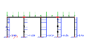
The following figures show results for the two loads.
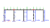
Axial force in beams for the two-span load.
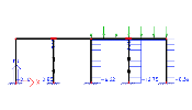
Axial force in beams for the one-span load.
Notice that there is no axial force in the left prop. The prop would get under tension if standard beams would be used for the whole structure. But as we defined the props as compression-only, the calculation removes the prop from the model once it finds that it gets under tension.
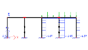
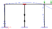
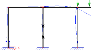
Deformation of the frame for the one-span load.
In this detail look you may clearly see that the horizontal beam is torn away from the top end of the prop.
Comparison with static linear calculation
The following set of pictures demonstrates what would have happened if just a linear calculation had been performed.
Axial force in beams for the two-span load.
This result is identical to the result of non-linear calculation for the first combination (the two-span load combination). In this load case both props are under compression. There is no need to take any corrective measures and therefore, the result of linear and non-linear calculation is identical.
Axial force in beams for the two-span load.
Axial force in beams for the two-span load in detail.
For the second load case representing the load acting on the right hand side span only, the situation is different. The left prop gets under tension and there is a tensile axial force in it.
Also the diagram of displacement shows that the prop remains "connected" to the horizontal beam, "holds" it firmly and influences the overall deformation of the frame.

