Tension only
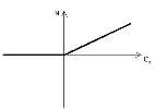
Tension-only 1D members (i.e. 1D members not able to bear any compression) show behaviour to the following stress-strain diagram:
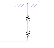
When inserted into the model, such a 1D member is marked with the following symbol (remember that in order to see the symbol, view parameters must be adjusted to show model data).
Note: The accuracy of the calculation may be affected by parameter Maximum iterations from dialogue Solver Setup.
The principle of tension-only beams is analogous to compression-only beams.
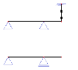
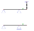
Let’s explain the principle on a simply supported beam with an overhanging load. Further, let’s assume that for some reason the vertical deflection of the free end must be limited. Therefore, a suspension cable is attached to the free end. The suspension cable will not prevent the beam end from "going up", but will significantly reduce any possible downward vertical deflection. Such a type of beam can be successfully modelled by means of a tension-only beam.
Our example will compare two variants: (i) one with the suspension rope, and (ii) one without it.
Similarly to compression-only beams, a special symbol is drawn on the tension-only beam. A pair of double-arrows whose tips point in opposite direction and away from each other forms the symbol.
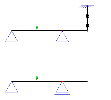
Let’s define load that will help us show the difference between the two variants.
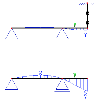
The first load case represents a vertical concentrated force located in the middle of the span between the supports.
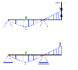
The second load case contains a vertical concentrated force located in the middle of the free "overhanging" end.
Let’s carry out a non-linear calculation with option Beam nonlinearity ON.
The results for the first load case will be identical for both variants: the suspension cable does not act and therefore does not affect the behaviour of the structure.
On the other hand, the results for the second load case are different. The vertical deflection of the free end for the "suspended" variant is significantly smaller than for the "non-suspended" variant.

