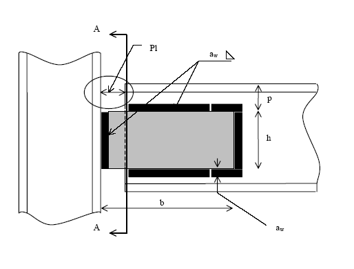
Welded pinned plate
Calculation design shear resistance VRd for connection element
The design shear resistance VRd is given by
![]()
with
|
fy |
the yield strength of the element |
|
γM0 |
the partial safety factor
|
|
A |
h t n |
|
W |
n t h² / 6 |
|
N |
the present normal force |
|
a |
b/2 |
|
σN |
the normal stress generated by normal force N |
|
n
|
the number of plates |
Calculation design shear resistance VRd for beam
The design shear resistance VRd is given by

with
|
fy |
the yield strength of the beam |
|
γM0 |
the partial safety factor |
|
r |
the radius of root fillet |
|
Av |
the shear area of the beam
|

Calculation design compression/tension resistance NRd for connection element
The design compression/tension resistance NRd is given by

with
|
fy |
the yield strength of the beam |
|
γM0 |
the partial safety factor |
|
A |
the area of the element (n h t) |
|
n
|
the number of plates |
Calculation design compression/tension resistance NRd for beam
The design compression/tension resistance NRd is given by

with
|
fy |
the yield strength of the beam element |
|
γM0 |
the partial safety factor |
|
A
|
the area of the beam |
Calculation design compression resistance NRd for column web
The design compression resistance NRd is given by the minimum of the crushing resistance Ry,Rd, the crippling resistance Ra,Rd and the buckling resistance Rb,Rd of the column web (see Ref.[2], 5.7.3., 5.7.4., 5.7.5)

Rb,Rd is obtained by considering the web as a virtual compression member with an effective breadth beff and buckling length d.

with
|
fy |
the yield strength of the beam element |
|
γM1 |
the partial safety factor |
|
tw |
the column web thickness |
|
ss |
the plate height |
|
bf |
the column flange width |
|
σf,Ed |
the longitudinal stress in the flange |
|
tf |
the column flange thickness |
|
d |
the column web depth |
|
a |
distance to the nearer end of the member |
|
h |
the column height |