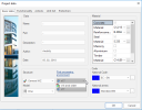
Basic project data
The basic data of a project describe the project and define some of its main parameters.
Project filename
It shows the name of the project.
Project data
This group of items allows the user to enter some statistical data about the project
|
Name |
name of the project E.g. Eddy Merckx's Airport – Brussel |
|
Part |
name of the project part, if the project is complex and consists of several partial sub-projects E.g. Western hall + connection footbridge |
|
Description |
E.g. variant A (underground parking, restaurants on first floor, check-in desks on second floor) |
|
Author |
name of the project author E.g. Sven Nijs |
|
Date |
date of the last project modification, or date of the program creation, etc. E.g. 02/02/02 |
Structure
Here, you can choose the type (or we can say "dimension") of the structure you want to model. Depending on the type selected, some of the functions and options of the program may be disabled or hidden (e.g. in the case of 2D frame oriented in plane XZ, the button for setting the sight of the model from the direction of X and Z axes respectively won't be present on the View toolbar). This feature leads to a significant simplification in the operation of the program for simpler types of structures. The functions and options that are not appropriate (are not possible practically) for the particular type are hidden and do not add to the complexity of the program. The idea behind this feature is: A complex task requires a complex tool, but a simple task can get by a simple tool.
Note: Item Structure is compulsory and the user has to make a choice from the available variants.
Material
This option tells the program which materials will be used for members of the structure. The advantage of this in advance selection is that the program functions working with materials will know, which material the user is interested in. Therefore, the functions will not offer other material types and, consequently, the dialogs, lists and similar items will be lucid and readable as much as possible.
If the user realises later that some other material type is necessary, it is of course possible to call the setting dialogue any time in the future and widen the selection of used material types.
Note: At the beginning, i.e. at the time when a new project is being created, it is necessary to select at least one material type.
Post-processing environment
Starting from version 17.0, it is possible to use a new post-processing environment for displaying of results. The new post-processing environment can be enabled in the Project dialogue.
|
v16 and earlier |
functions for the evaluation of results are consistent with the appearance in previous versions (i.e. v16 and older) |
|
v17 |
enhanced methods and possibilities of drawing style and other options for results are available |
Note: Post-processing environment v17 covers linear calculation (except prestressing), linear stability, nonlinear calculation (beam local nonlinearity, 2nd order calculation, Initial deformation and curvature) and modal analysis. Eurocode building standards for concrete and steel are supported. Please, check content of your Engineering Report after calculation. If you want to use advance analysis types change Post-processing environment to v16 and older.
Detailed description can be found in chapter ""Default" Post-processing environment "
Model
|
One |
the project will contain a single model of a structure |
|
Construction stages |
the project will represent modelling of construction stages appearing during the execution of the structure |
Code
The selection of the active code determines how the program deals with data related to a specific technical standard. In practice it means that the code selection affects:
-
the materials offered as code-related materials, e.g. steel or concrete grades, etc.
-
the procedures, algorithms and possible parameters performing and necessary to perform code checks.
Note: The choice of a particular national standard may have an effect on the layout and even functionality of numerous functions. E.g. functions like Load case and Load group have got parameters that depend on the current code of the project. That means that these function offer the user different parameters for e.g. Czech standard than for let’s say Eurocode. Also the functionality of some functions or services is different for different codes.
The procedure for setting the parameters is the same as for other project parameters.

