Layout and operation of a database manager
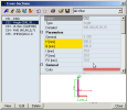
A manager consists basically of the following controls:
|
List of defined entities of a particular database |
The list shows all the entities related to the database of the manager that have been defined in the current project so far. |
|
Property table |
This table shows a brief summary of parameters for the database entity that is just selected in the list of already defined entities (see above). |
|
Graphical window |
This window displays a drawing of the database entity whose parameters are just listed in the property table. |
|
Control buttons |
The buttons provide the access to the functions that are accessible from within the particular manager. |
|
Filter |
The filter allows for a readable representation of data in the Manager. |
List of defined database entities
The list summarises all the database entities that has been defined in the project. Most often, the list contains names of the entities. However, if useful and practical, some additional information may be added next to the name.
Property table
The property table displays parameters for the entity that is selected in the list of defined entities. It provides for a quick review of the parameter values. Some of the parameters can also be edited here. But normally, the modification of the parameters is performed in the editing dialogue for a particular entity type.
Graphical window
This window contains a schematic drawing of the database entity the parameters of which are presented in the property table. This window is fitted with a pop-up menu. The menu offers the user some important functions related to the displayed entity.
Control buttons
There are several control buttons in the Manager that allow to user to use various actions that may be performed with database entities.
Example - function Unify
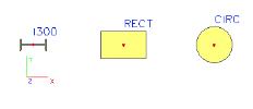
Let us suppose that we have defined three beams, each of them of a different cross-section.
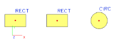
Later you may want to unify the section of the two left beams and have both of them of rectangular cross-section. Of course, you may edit the properties of the beam and change its cross-section. On the other hand, sometimes it may be useful to "unify" the sections (and if required, get rid of the abandoned cross-section type, that can be automatically deleted from the database).
You call the Unify function to merge two cross-sections into one. In our example do the following:
-
select the rectangular cross-section,
-
call function Unify,
-
select the I section,
-
confirm with OK,
-
the I-section is removed from the project database, two beams are assigned the same rectangular cross-section.
Filter
The filter provides for more readable representation of data in the Manager if the current project contains an excessive number of defined entities of the particular type. The filter allows the user to set a limited set of entities that are displayed in the List of defined entities. The entities that do not meet the chosen criterion are "removed" from the list, but still remain normally defined in the project.
Note: Some specific database managers may contain additional functionality. It is added in the form of additional control buttons.
Name
Note: The name of any item in any manager should be up to 8 characters in length. Longer names should not be used and may be truncated by the program.


