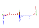
Analysis of a beam on elastic foundation versus mesh size
As stated earlier, finite element mesh where one 1D finite element corresponds to one beam member is satisfactory as far as the precision of results is concerned. However, and it was stated as well, there are exceptions to this rule.
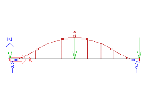
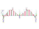
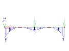
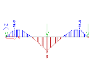
One of the exceptions is a beam laid on elastic foundation. The following table compares results for three different finite element divisions.
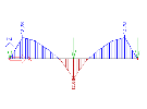
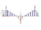
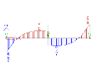
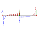
The table shown diagrams of vertical displacement, bending moment and shear force for three different meshes. The first one has got only one finite element on the beam. The other one has got two elements generated on the beam. The last one then shows results for a very fine mesh. It is clear that the distribution of both displacement and internal forces is considerably affected by the "coarseness" of the mesh. The reason is that for a beam supported by a foundation strip, the deflection curve (displacement diagram) is no longer a cubic parabola applied in the implemented finite element.
Therefore, it is important to remember that the finite element mesh fully sufficient for "standard" beams is completely unsuitable for analysis of members on foundation. The default settings reflect this phenomenon and are tailored for most of common structures. In some special cases however, additional, user-made, tuning of the mesh generation parameters may be necessary in order to obtain relevant and accurate results.
Vertical displacement
|
FE per beam |
|
|
1 |
|
|
2 |
|
|
32 |
Bending moment
|
FE per beam |
|
|
1 |
|
|
2 |
|
|
32 |
Shear force
|
FE per beam |
|
|
1 |
|
|
2 |
|
|
32 |

