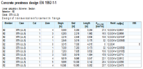
Design of transverse reinforcement in flange of cross-section according to EN 1992-1-1, chapter 6.2.4
Abstract
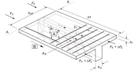
The subject of this manual is the design of transverse reinforcement in the flange of cross-sections according to EN 1992-1-1, chapter 6.2.4. Transverse reinforcement is reinforcement in the flange perpendicular to the longitudinal axis of the member (x-axis in the local coordinate system). The influence of longitudinal shear (the shear between the web and flange in the direction of the longitudinal axis of the member) and transverse bending moment (bending moment around the longitudinal axis of the member) can be taken into account in the design. Transverse reinforcement for the longitudinal shear is designed directly by the program, but transverse reinforcement for the transverse bending moment has to be input manually by users using the REDES function. Only the general cross-section is supported for this design, standard cross-section types have to be convert to the general cross-section. The cuts in general cross-section and special parameters have to be defined, if the user wants to design the transverse reinforcement.
The following steps for the design of the transverse reinforcement have to be performed:
Definition of a cut and special parameters in the cross-section (chapter 2).
Definition or change of input parameters in concrete member data and concrete setup (chapter 3).
Input of transverse bending reinforcement (chapter 4).
Calculation of longitudinal shear stress (chapter 5).
Design of transverse reinforcement in the flange (chapter 6).
Supported code: only EN 1992-1-1
Supported member: concrete 1D beams
Supported cross-sections: general cross-section and cross-section from Product range library with cuts and with special parameters
Supported procedure: only design (check is not supported)
Definition of cuts and special parameters in the cross-section
The cuts and special parameters have to be defined for the calculation of transverse reinforcement in the flange of a cross-section. We support:
only general cross-sections (with one or more phases), where special parameters and cuts in cross-section have to be defined manually by the user,
cross-sections from Product range library, where special parameters and cuts in the cross-section are predefined.
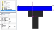
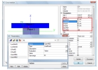
Cuts in the cross-section on position of web-flange joint has to be input by the user (several cuts can be defined in one cross-section) in dialog Cross-section editor via item Add cut.
The standard cross-section can be used for the design of transverse bending reinforcement after converting the cross-section to a general cross-section.
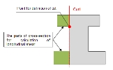
All parts of the cross-section that are cut by the cut are taken into account in the calculation of longitudinal shear.
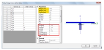
Special parameters in dialog Parameter in General cross-section editor have to be defined:
Boolean parameter LonShrXX
if parameter is YES, transverse bending reinforcement for cut with ID = XX will be designed (for example, if parameter LonShr01 is defined and it has value ON, then for cut number 1 (ID = 1) the transverse bending reinforcement is designed),
if this parameter is not defined, the transverse bending reinforcement is not designed,
the number of LonShrXX parameters should be the same as the number of predefined cuts,
if the user adds a new cut into the general cross-section, parameter LonShrXX is not created by program automatically, but the parameter must be defined manually by the user.
Boolean parameter LPartXX
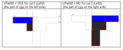
if parameter is YES, the part of the cross-section on the left side from the cut with ID=XX is used for the integration of internal forces (for the calculation of the longitudinal shear),
if this parameter is not defined, the part of the cross-section on the left side from the cut is taken into account for the integration of internal forces,
the number of the parameters should be the same as the number of predefined cuts,
if the user adds a new cut in a general cross-section, the LPartXX parameter is not created by the program automatically, but the parameter must be defined manually by the user.
CSS length parameter UserHfXX :
If UserHfXX = 0, then the length of cut with ID =XX across the cross-section is automatically calculated from the geometry of the cut,
If UserHfXX> 0, the value defined via parameter UserHfXX is used for the calculation,
if this parameter is not defined, then the length of the cut across the cross-section is automatically calculated from the geometry of the cut,
the number of the parameters should be the same as the number of predefined cuts,
if the user adds a new cut to a general cross-section, parameter UserHfXX is not created by the program automatically, but the parameter must be defined manually by the user.
The defined parameters appear in the Cross-section dialog and can be edited.
Definition or change of input parameters in concrete member data and concrete setup
Concrete setup
The parameters which have influence on the design of transverse bending reinforcement are under Concrete setup > ULS > Shear > 1D structure:
Compression flange>theta,
Tension flange>theta,
Shear between web and flange>Calculate shear stress in distances dx/h,
Shear between web and flange>Number of zones for output.
The angle of the concrete compression strut for flange in tension and compression can be edited in group Angle between the concrete compression strut and beam axis by using either angle or cotangent of angle. The angles are used in formulas 6.21 and 6.22 in EN -1992-1-1 (see chapter 6.2). The limit values of angle theta are defined in ULS > National annex. Also defined is the coefficient for the calculation of longitudinal shear stress resisted by the concrete k (see chapter 6.1.2(6) in EN 1992-1-1):
k – coefficient for calculation of longitudinal shear resisted by concrete
theta_min_w - min. angle between the concrete compression strut and the axis beam for web
theta_min_c - min. angle between the concrete compression strut and the axis beam for compression flange
theta_min_t - min. angle between the concrete compression strut and the axis beam for tension flange
theta_max_w - max. angle between the concrete compression strut and the axis beam for web
theta_max_f - min. angle between the concrete compression strut and the axis beam for flange
In group Shear between web and flange there are two parameters:
Calculate shear stress in distance dx /h
this property defines the distance of the cut measured along the beam for calculation of longitudinal shear stress, see formula 6.20 in EN 1992-1-1
default value is 0,1 => dx(Dx) = 0,1·h
Number of zones for output
the value is used in the numerical zone-output and it defines the number of zones (see chapter 5)
default value is 5
Concrete member data
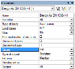
There is only one property in concrete member data that is used for the calculation of transverse reinforcement in the flange in group Transverse reinforcement in flange:
Diameter
the value represents the diameter of transverse bending reinforcement which is used for the design of reinforcement for longitudinal shear stress,
the default value is read from Concrete setup > Design default > Beams > Stirrup
If concrete member data are not defined, the diameter of the transverse reinforcement designed for longitudinal shear stress is read from Concrete setup > Design default > Beams > Stirrup.
Input of transverse bending reinforcement
Input of reinforcement
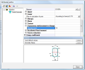
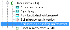
The transverse bending reinforcement can be defined via REDES using item Add transverse bending reinforcement in Concrete Advanced tree > REDES (without As) or using icon Transverse bending reinf.
,Note
The reinforcement is input in a similar way to a standard stirrup zone.
The procedure and conditions for input of transverse bending reinforcement
the user selects the beam for where the reinforcement is to be defined,
the reinforcement is automatically assigned to all cuts with parameter LonShrXX = YES (assigning of the reinforcement to the cut can be changed in properties of reinforcement via property List of cuts),
for each cut only one span of transverse bending reinforcement can be defined,
the material of reinforcement and diameter of the bars are read from Concrete Member Data or from Concrete Setup,
different property can be defined for each span of transverse bending reinforcement,
the reinforcement is input on the whole beam and its position cannot be edited,
openings are not taken into account for the transverse bending reinforcement,
the number of spans of transverse bending reinforcement is the same as the number of spans of an arbitrary beams (In SCIA Engineer, the span is an expression for one part (prismatic or haunched) of a beam with an arbitrary cross-section),
the number of zones (one span can contain several zones) of transverse bending reinforcement depends on the spans of arbitrary beams and on the position of supports,
for a prismatic beam: number of zones = number of internal supports +1
for an arbitrary beam (zones are read from geometry of the arbitrary beam): number of zones = number of spans + number of internal supports.
A member with 4 spans of transverse bending reinforcement and 6 zones
Properties of transverse bending reinforcement in flange
The transverse bending reinforcement in each span has the following properties.
|
Detailing - if check box is ON, than reinforcement is not taken into account, but is used for bill of reinforcement.
Active - this check box is active only if Detailing = ON. If Active = OFF, than reinforcement is not used in bill of reinforcement.
Material - material of transverse bending reinforcement, read from concrete member data or concrete setup.
Diameter - diameter of transverse bending reinforcement, read from concrete member data or concrete setup.
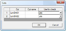
List of cuts - the dialog for assigning of transverse bending reinforcement to defined cuts in the cross-section, see dialog below.
Length - length of transverse bending reinforcement, this value is not considered in the design, it is an important value for bill of reinforcement.
Drawing offset Y(Z) - the reinforcement is presented only schematically in the graphical window (the default is in centroid of the cross-section). This value is used for better graphical representation, if several spans of transverse bending reinforcement are defined in one span of an arbitrary beam. The position of the reinforcement is not considered in the design. The reinforcement is assigned to the cut of flange via property List of cuts.
Edit distance - the dialog for editing of distance of reinforcement and creating/deleting of new parts for zones of reinforcement.
|
Dialog for assigning transverse bending reinforcement to cut
-
only the cuts with parameter LonShrXX = YES (active cut) are presented in this dialog,
-
the user can select for which cuts the defined span of transverse bending reinforcement are used (column Use for check),
-
for each cut only one span of transverse bending reinforcement can be defined,
-
the program gives a warnings if:
-
-
no cut with parameter LonShrXX = YES is defined,
-
reinforcement is assigned to all active cuts on the member (span of arbitrary beam)
-
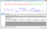
Edit distance of transverse bending reinforcement
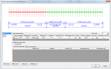
The default distance of transverse bending reinforcement after input is 300 mm. The distance can be edited and changed using action button Edit distance in the properties of the span of transverse bending reinforcement.
The span may contain several zones (it depends on the number of supports). The zone can be created or deleted using button New zone and Delete zone in the bottom left corner of the dialog. For each zone the basic reinforcement is defined and it is the same over the whole length of the zone. New parts can be created/deleted for each zone using buttons New part or Delete part. The transverse bending reinforcement can be symmetrical in the zone if check box "Symmetrical" is ON.
Properties in the table for the definition of basic reinforcement the in zone:

Length (Lzone)- length of zone for which basic reinforcement is defined.
Diameter (ds,b)- the diameter of transverse bending reinforcement in selected zone.
Input type- type for definition of transverse bending reinforcement in selected zone. There are three possibilities:
-
Distance- the area of reinforcement is defined by centre-to-centre distance of bars of transverse bending reinforcement.
-
Numbers- the area of reinforcement is defined by the number of bars per meter of the zone.
-
Area- the area of reinforcement is defined by the area of bars per meter of the zone.
Distance (sb,zone )- is the centre-to-centre distance of bars of transverse bending reinforcement in longitudinal direction of the member. This value is calculated from input parameters.
-
for Input type = Distance, the distance of reinforcement is input directly by the user to the column Distance.
-
for Input type = Numbers, the distance of reinforcement is calculated from the number of links per meter of the zone:

-
for Input type = Area, the distance of reinforcement is calculated from the area reinforcement per meter of the zone:

Numbers (nb,zone) - the number of bars of transverse bending reinforcement per meter of the zone:
-
for Input type = Distance, the number of bars is calculated from the distance of bars:

for Input type = Numbers, the number of bars is input directly by the user to the column Numbers.
for Input type = Area, the number of bars is calculated from the area of reinforcement per meter of the zone:

Area (Ab,zone) -is the area of bars of transverse bending reinforcement per meter of the zone:
-
for Input type = Distance, the area of reinforcement is calculated from the distance of bars:

for Input type = Numbers, the area of reinforcement is calculated from the number of bars:

-
for Input type = Area, the area of the reinforcement is input directly by the user to the column Area.
Real distance (sf,b)- is centre-to-centre distance of bars of transverse bending reinforcement in longitudinal direction of the member. This value can be different than value sb,zone, because this value is calculated for number of bars rounded to an integer:

Distance to begin (sb,begin) - the distance of the axis of the first bar of transverse bending reinforcement from the beginning of the zone. The value can be:
-
input by user if check box By user = Yes,
-
calculated automatically, if check By user = No. The value depends on default settings defined in Concrete setup > Detailing provisions > REDES > group Distance of the first stirrup from begin/end of the zone. For calculation the following can be used:
-
-
value sf,b from the basic reinforcement, if no parts are defined in the zone,
-
value sf,b of the first part at the beginning of the zone, if some parts are defined in the zone.
-
-
Distance to end (sb,end) - the distance of the axis of the first bar of transverse bending reinforcement from the end of the zone. The value can be:
-
-
input by user, if check box By user = Yes,
-
calculated automatically, if check By user = No. The value depends on default settings defined in Concrete setup > Detailing provisions > REDES > group Distance of the first stirrup from begin/end of the zone. For calculation the following can be used:
-
-
value sf,b from the basic reinforcement, if no parts are defined in zone,
-
value sf,b of the first part at end of the zone, if some parts are defined in the zone.
-
-
Properties in group Additional reinforcement of the zone:
Symmetrical
If the check box is ON, then the transverse bending reinforcement in parts at the beginning and end of the zone are symmetrical and defined only in one table.
If the check box is OFF, then the transverse bending reinforcement in parts at the beginning and end of the zone can be different and it is defined in two different tables.
Table for the definition of the part contains the following properties:
Distance (sb,part ) - the centre-to-centre distance of bars of transverse bending reinforcement in longitudinal direction of the member in the part. This value is defined for the whole length of the part.
for Input type = Distance, the distance of reinforcement is input directly by the user to the column Distance.
for Input type = Numbers, the distance of reinforcement is calculated from the number of bars per total distance of the part:

for Input type = Area, the distance of reinforcement is calculated from the area of reinforcement per total distance of the part:

Numbers (nb,part) -the number of bars of transverse bending reinforcement in the part of the zone. The number of the bars is defined for the whole length of the part:
-
for Input type = Distance, the number of bars is calculated from the distance of bars:

for Input type = Numbers, the number of bars is input directly by the user to the column Numbers. The input value is rounded up to an integer.
for Input type = Area, the number of bars is calculated from the area of reinforcement which is defined in the part of the zone:

Area (Ab,part) –the area of bars of transverse bending reinforcement in the part of the zone. The area of the reinforcement is defined for the whole length of the part:
-
for Input type = Distance, the area of reinforcement is calculated from the distance of bars in the part:

for Input type = Numbers, the area of reinforcement is calculated from the number of bars in the part:

-
for Input type = Area, the area of the reinforcement is input directly by the user to the column Area.

-
Real distance (sf,b)- the centre-to-centre distance of bars of transverse bending reinforcement in longitudinal direction of the member in the part of the zone. This value can be different than the value of sb,part, because this value is calculated for the number of bars rounded to integer.

-
Total distance (Lp)- is the length of the part.
Numerical output of transverse bending reinforcement
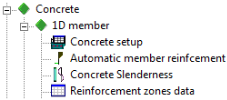
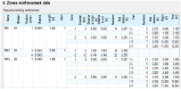
The input properties of transverse bending reinforcement can be printed in the Document via item Reinforcement zones data.
There are presented general properties, properties of each zone and each parts of the zone.
Note: In column Part all parts of the zone are presented, with letter "L" meaning the part on the left side (beginning of the zone) and letter "R" meaning the part on the right side (end of the zone).
Integration of internal forces in shear calculation
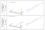
The longitudinal shear stress (in the direction of the x-axis of the local coordinate system of the member) between the web and flange is calculated by integration of internal forces. There are the following preconditions:
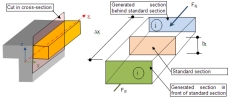
- The change of normal force DFd is calculated in the part of flange bounded by the cut in each section
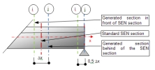
- The longitudinal shear stress is calculated in standard result sections, but the integration of internal forces is made in two generated sections (in front of and behind the standard result section) in the longitudinal direction. The distance between the generated sections is Dx.
- At the end of the member only one section on the side of the member is generated, the second section is a standard result section. The distance of the sections in this case is only 0.5 Dx.
- The integration of internal forces in generated sections is done only for the part of the cross-section on the left or right side from the cut. It depends on the value of parameter LPartXX, see chapter 2.
- The strain-stress diagram for the integration is taken from the ULS equilibrium response, but:
- influence of additional tension force caused by shear and torsion ("shifting") is not taken into account,
- reduction of the stress-strain diagram caused by anchorage is not taken into account.
Calculation of normal forces in the generated section
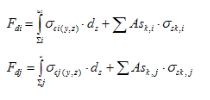
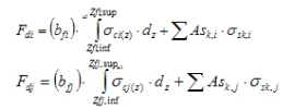
Normal forces in the generated section is calculated according to formulas below.
In general:
In the particular case of a beam with a constant width bf under bending moment My, the formula is:
where
|
|
is related to the detached area (by the cut) at section i |
|
|
is related to the detached area (by the cut) at section j |
|
|
is the concrete stress in element « ds » at coordinates (y,z) in area Si |
|
|
is the concrete stress in element « ds » at coordinates (y,z) in area Sj |
|
|
is the user real (REDES bars or FREE bars) reinforcement area or area of prestressed reinforcement in area Si |
|
|
is the user real (REDES bars or FREE bars) reinforcement area or area of prestressed reinforcement in area Sj |
|
|
is the stress in reinforcement Ask,i |
|
|
is the stress in reinforcement Ask,j |
|
|
z-coordinate of the bottom and top (resp.) fibre of detached area Si |
|
|
z-coordinate of the bottom and top (resp.) fibre of detached area Sj |
Calculation of longitudinal shear stress
It is calculated according to formula 6.20 in EN 1992-1-1

where
|
hf |
is the height of flange determined in the position of the standard result section |
|
|
is the distance of two adjacent generated sections, Dx = 0.1·h, where coefficient 0.1 can be changed in Concrete Setup, see chapter 3.1 |
|
h |
is the height of cross-section in standard result section |
|
|
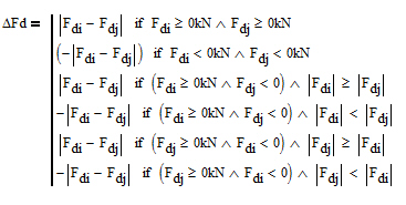
is the change of normal force in the flange over the length. The value and sign of the change of normal forces is calculated according to procedure below if DFd < 0 kN the flange is in compression if DFd ≥ 0 kN the flange is in tension |
Design of transverse reinforcement in flange
The transverse bending reinforcement can be designed in two services:
- Design
- Design of non-prestressed reinforcement in prestressed css
Changes in the service for design of reinforcement
There are following changes in services for design As in comparison with previous versions of the program:
A new check box Use named cuts,
default value is OFF,
if the check box = OFF, then the extreme value of Asf from all active cuts (cuts with parameter LonShrXX = YES) is presented in the graphical and numerical output,
if the check box = ON, then the extreme value of Asf of the selected active named cut is presented in the graphical and numerical output.
A new combo box Named cut where the list of named active cuts appears. This item is active only if check box Use named cut is ON,
A new combo box Type of output for setting the type of numerical output with two items:
Standard – area of Asf is evaluated in each section of the member,
Zone output –area of Asf is evaluated in zones (local extreme), see chapter 6.3.2. The number of zones can be changed in Concrete setup > ULS > Shear > 1D structures > group Shear between web and flange (chapter 3.1).
A new value Asf is added in combo box Value for design of the transverse reinforcement into flange.
Procedure for the design
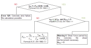
Four types of reinforcement are calculated and evaluated:
- transverse reinforcement designed for longitudinal shear stress, Asf,s
- transverse reinforcement designed for transverse bending moment, Asf,b
- transverse reinforcement designed for transverse bending and longitudinal shear stress, Asf,sb
- transverse reinforcement designed for longitudinal shear stress complementary to transverse bending reinforcement, Asf,c
The transverse reinforcement designed for longitudinal shear stress, Asf,s
This type of reinforcement (value Asf,s) is designed if the following conditions are fulfilled:
- for non-prestressed member (service Design As)
- the user real non-prestressed reinforcement (REDES bars or FREE bars) is input in the selected member,
- the check box Take into account long.user reinforcement for design calc in Concrete setup > General > Calculation is ON,
- the ULS equilibrium is found,
- the material grade of the transverse bending reinforcement (defined in the REDES) and transverse reinforcement designed for longitudinal shear stress is the same,
- for prestressed member (service Design of non-prestressed reinforcement in prestressed css)
- prestressed reinforcement (tendons or strand pattern) is input in the selected member,
- the ULS equilibrium is found,
- the material grade of the transverse bending reinforcement (defined in the REDES) and transverse reinforcement designed for longitudinal shear stress is the same.
Procedure:
where
|
vEd |
the longitudinal shear stress |
|
n |
the strength reduction factor for concrete cracked in shear (formula 6.6N, EN 1992-1-1) |
|
fcd |
design compressive strength of the concrete |
|
angle between the concrete compression strut and beam axis, the value for calculation and limit value can be set in Concrete Setup, see chapter 3.1 |
|
|
k |
coefficient for calculation of longitudinal shear stress resisted by concrete, the value can be edited in Concrete Setup, see chapter 3.1 |
|
fctd |
design tensile strength of concrete |
|
Asf,b |
the transverse reinforcement designed for transverse bending moment per meter (the reinforcement input in REDES, see chapter 4) |
|
hf |
height of flange determined in position of the standard result section |
|
fyd |
design yield strength of reinforcement |
|
Asf |
the area of a single reinforcement bar for longitudinal shear
|
|
Asf,s |
the transverse reinforcement designed for longitudinal shear stress per meter |
|
sf,s |
distance of transverse reinforcement designed for longitudinal shear stress |
|
ds,s |
diameter of transverse reinforcement designed for longitudinal shear stress |
The transverse reinforcement designed for transverse bending moment, Asf,b
The area of transverse bending reinforcement is not calculated, but it has to be inputted by user via REDES. The important parameter for calculation of Asf,bis the real distance of transverse bending reinforcement.

where
|
sf,b |
real distance of transverse bending reinforcement read for each zone and part of the zone from REDES, see chapter 4.3 |
|
ds,b |
diameter of transverse reinforcement input in REDES for each zone (see chapter 4.3) |
The transverse reinforcement designed for transverse bending and longitudinal shear stress, Asf,sb
Design of transverse reinforcement in flange for transverse bending and longitudinal shear stress Asf,b is calculated according to chapter 6.2.4(5) in EN 1992-1-1.

The transverse reinforcement designed for longitudinal shear stress complementary to transverse bending reinforcement Asf,c
It is the transverse bending reinforcement designed for longitudinal shear that has to be added to the transverse bending reinforcement input in REDES.

where
|
sf,c |
distance of transverse reinforcement designed for longitudinal shear stress complementary to transverse bending reinforcement |
|
ds,s |
diameter of transverse reinforcement designed for longitudinal shear stress |
Output of designed reinforcement
Numerical and graphical output are supported for the designed transverse reinforcement.
Only value Asf,sb is presented in the graphical output where the results are evaluated in the standard result section (standard output).
Numerical output can be presented in the member design or in the single check (detailed result in selected standard result section).
The user can select two types of numerical output in member design:
Standard – area of all types of reinforcement are evaluated in each section of the member.
-
Zone output – only area of Asf,c is evaluated in the zones(local extreme).
Member design - Standard output
The results will be evaluated in each standard result section.
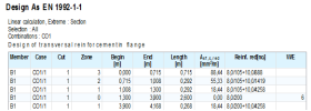
The transverse reinforcement in flange for transverse bending and longitudinal shear stress is presented in the graphical and numerical output.
The following values are presented in Default table
|
Member |
the name and number of the member |
|
dx |
position of standard result section |
|
Case |
|
|
Cut |
the number (ID) of extreme cut in the cross-section with extreme value of designed transverse reinforcement |
|
vEd |
the longitudinal shear stress |
|
vRd,c |
the longitudinal shear stress carried by concrete according to 6.2.4(6) |
|
vRd.max |
the maximum longitudinal shear stress to prevent crushing of compression struts in the flange calculated according to 6.22 |
|
Asf,b |
the transverse reinforcement designed for transverse bending moment per meter |
|
Asf,s |
the transverse reinforcement designed for longitudinal shear stress per meter |
|
Asf,c |
the transverse reinforcement designed for longitudinal shear stress per meter complementary to transverse bending reinforcement. |
|
Asf,sb |
the transverse reinforcement designed for transverse bending and longitudinal shear stress per meter |
|
Reinf |
the diameter and distance of bars if Asf,c = 0 and Asf,b = 0 Reinf : empty if Asf,c > 0 and Asf,b = 0 Reinf : ds,s/sf,c if Asf,c = 0 and Asf,b > 0 Reinf : ds,b/sf,b if Asf,c > 0 and Asf,b > 0 Reinf : ds,b/sf,b + ds,s/sf,c |
|
W/E |
the number of a warning or error |
The user can add other values (table below) to the numerical table using the Table composer.
|
|
the change of normal force in the part of flange bounded by cut |
|
hf |
the thickness of flange at the junctions |
|
Dx
|
the length for calculation of change of normal force in the part of flange bounded by cut |
|
n |
the strength reduction factor for concrete cracked in shear |
|
|
angle between the concrete compression strut and beam axis |
|
Type |
type of flanges (T = in tension, C= in compression) |
|
ds,s |
diameter of transverse reinforcement designed for longitudinal shear stress |
|
ds,b |
diameter of transverse reinforcement designed for transverse bending moment |
|
sf,s |
distance of transverse reinforcement designed for longitudinal shear stress |
|
sf,b |
distance of transverse reinforcement designed for transverse bending moment |
|
sf,c |
distance of transverse reinforcement designed for longitudinal shear stress complementary to transverse bending reinforcement |
Member design - zone output
The output is independent on standard result sections.
This output is presented only in numerical output.
The envelope area of Asf,sb without zones is presented in graphical result only.
The following values are presented in "default" table
|
Member |
the name and number of the member |
|
dx |
position of standard result section |
|
Case |
type and name of extreme load case/combination/class |
|
Cut |
the number (ID) of extreme cut in the cross-section with extreme value of designed transverse reinforcement |
|
Zone |
number of zone, |
|
Begin |
position of beginning of zone |
|
End |
position of end of zone |
|
Length |
length of zone (distance between beginning and end of the zone) |
|
Asf,c,red |
the average area of transverse reinforcement in zone designed for longitudinal shear stress per meter, complementary to transverse bending reinforcement. |
|
Reinf |
the diameter and distance of bars if Asf,c = 0 and Asf,b = 0 Reinf : empty if Asf,c > 0 and Asf,b = 0 Reinf : ds,s/sf,c,red if Asf,c = 0 and Asf,b > 0 Reinf : ds,b/sf,b if Asf,c > 0 and Asf,b > 0 Reinf : ds,b/sf,b + ds,s/sf,c,red |
|
W/E |
the number of a warning or error |
The value sf,c,red is the distance of transverse reinforcement calculated for Asf,c,red.

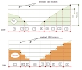
Procedure for calculation of zone output on the member
The envelope area of Asf,cis calculated in each standard result section for selected load/combination/class.
The maximum value (Asf,c,max) from the envelope area of Asf,c is found on the member.
The value Asf,c,max is divided to horizontal strips (straight horizontal lines) with same height hzone = Asf,c,max /n (the value n is the number of zones for numerical output and can be edited in Concrete setup > ULS > Shear > group "Shear between web and flange").
The intersections of straight horizontal lines with envelope area of Asf,c is found.
The vertical zone is created between to intersections.
The average value Asf,c,red from area of Asf,c is calculated in each zone and this value is presented in the output table.
Single design
Detailed design of member can be run via action button Single Check in the service Design As. The numerical output is presented in:
text prompt - only value Asf,sb and warnings/ errors,
preview - the similar table as in member design for standard output with or without explanations of symbols is presented. The table is presented if in dialog Change of setup item "Transversal reinforcement in flange is ON.
XML and parameterization
All values for transverse bending reinforcement can be parameterized and changed via XML.
Definition of new terms
|
Product range library |
a library of general cross-sections with parameterized dimensions and additional parameters so that it is tailor-made for KP1. Detailed description will be provided as a part of the documentation. |
|
REDES |
a module of SCIA Engineer for the definition and drawing of real non-prestressed reinforcement |
Examples
Example 1
The single beam with prestressed reinforcement (benchmark E01) and with construction stages calculated via TDA analysis.
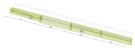
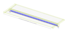
The model of structure
Input of parameters for design transverse bending reinforcement in flange
The cross-sections were loaded from product range library, where the cuts and special parameters are already predefined. The parameters are necessary for the design of transverse bending reinforcement.
The predefined cuts in cross-section from product range library
The list of cuts from the product range library for KP1.
Input transverse bending reinforcement Asf,b
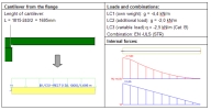
The transverse reinforcement designed for transverse bending moment is not automatically designed by the program. This reinforcement can be calculated manually and input to flange via REDES. The reinforcement was designed manually as upper reinforcement to cantilever (one part of flange)
Design reinforcement to cantilever and check for shear:
The beam was modeled as a beam slab with the following input parameters for the design of reinforcement:
ds = 12 mm (B500A), concrete cover = 30 mm, concrete C30/37
Design of reinforcement
Check of shear
VEd < VRd,c, which means that shear force is carried by concrete and thickness of flange (cantilever) is OK, but it is necessary to input transverse bending reinforcement f12(B500(A))-250mm/m via REDES.
The transverse bending reinforcement is input only in member B2 and this reinforcement is automatically assigned to all active cuts.
Graphical presentation of transverse bending reinforcement
There are three spans in member B2, because there are defined some internal supports as props during casting of the slab. The reinforcement is input via Input type = Distance, where distance = 250 mm. Real distance for each zone can be different than the input value and it depends on the length of the span and on the distance to the beginning/end. For example, the real distance of bars for zone 1 is 0,241 m (see formula below)

Calculated transverse bending reinforcement for longitudinal shear
The extreme values from all active cuts are evaluated in service Design As (the check box Use named cuts is OFF).
The graphical presentation of areaAsf,bwithout non-prestressed lower reinforcement
The numerical presentation of transverse bending reinforcement without non-prestressed lower reinforcement
There is error 896 (Forces are zero or no equilibrium not found, check if longitudinal reinforcement exists) in the middle of the beam, therefore we have to input lower non-prestressed reinforcement (3f20 B500B). The area of Asf,sb with non-prestressed lower reinforcement is the following.
The numerical presentation of transverse bending reinforcement without non-prestressed lower reinforcement for standard output (extreme = member)
The numerical presentation of transverse bending reinforcement without non-prestressed lower reinforcement for zone output (number of zone =5 )
The check results in section x = 9,913 m
Calculation of longitudinal shear
- the height of section h = 630 mm
- dx/h = 0.1 => Dx(dx) = 0.1·h =0,1·630 =63 mm (Concrete setup > ULS > Shear >1D structures)
- height of flange hf = 130 mm
The resultant of normal force in generated sections in front (x-0.5Dx) and behind (x+0.5Dx) of the standard result section (x = 9,913 m).
Because Fdi < 0 kN and Fdj< 0, the flange is in compression and the change of normal force is calculated according to formula:

The longitudinal shear is calculated according to formula:

Design of transverse reinforcement designed for longitudinal shear stress Asf,s
- characteristic compressive cylinder strength fck = 30 MPa
- design compressive strength fcd = 20 MPa
- angle of compression strut for flange in compression qf = 40 deg
- strength reduction factor for concrete cracked in shear

- design tensile strength of the concrete fctd = 1,33 MPa
- coefficient for calculation of longitudinal shear stress carried by concrete k = 0,4 (Concrete setup > ULS > National annex)
- design yield strength of transverse reinforcement designed for longitudinal shear fyd =434,8 MPa (loaded from concrete setup or from concrete member data if exist)
Calculation of the maximum longitudinal shear stress to prevent crushing of compression struts in the flange

=> the condition is satisfied (no crushing of compression strut)
Calculation of the longitudinal shear stress carried by concrete

=> shear stress in not carried by the concrete, transverse reinforcement designed for longitudinal shear is necessary
Design of reinforcement:

Design of transverse reinforcement designed for transverse bending reinforcement Asf,b
diameter of transverse bending reinforcement dsb =12 mm (taken from REDES, zone = 3)
real distance of transverse bending reinfor. sfb = 0,241 m (taken from REDES, zone = 3)

Design of transverse reinforcement designed for transverse bending and longitudinal shear stress Asf,sb

Design of transverse reinforcement designed for longitudinal shear stress per meter, complementary to transverse bending reinforcement Asf,c
diameter of transverse reinforcement designed for longitudinal shear stress dss =12 m ( loaded from concrete setup or from concrete member data if exist)

It is necessary to add additional reinforcement (f12/358) to reinforcement designed to transverse bending moment (f12/241) in section x = 9,913 m.

