01/01/2010
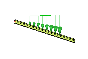
Line force load models load distributed over a 1D member. It may be action along the whole 1D member or only on its part. Parameters of point load applied into a node are:
|
||||||| .merge-left.r4751
| |
|
=======
| |
|
>>>>>>> .merge-right.r4752
Name |
Is used for the identification of the load. |
|
Specifies the base direction of the load. The direction may further specified by the Angle item. |
|
|
Type |
The point load may be a force load, wind load, snow load, or predefined load. |
|
Specifies the angle by which the load is rotated from its basic direction. |
|
|
Distribution |
The load may be either constant along the 1D member or linearly variable (trapezoidal). |
|
Specifies the size of the load. |
|
|
Defines the co-ordinate system in which the load is applied. |
|
|
Bottom flange |
This feature is available only for old code EC - EVN. Defines the distribution of load on a built-in 1D member – see Out-of-balance factor below. |
|
Load above joint |
If ON, then this force will be considered in the check of longitudinal shear stress in the joint. It has meaning only for phased cross-sections. |
|
Q factor |
This feature is available only for old code EC - EVN and it is taken into account only for old steel checks according this code. Defines the Out-of-balance factor – see below. |
|
Specifies whether the load is "put directly on an inclined 1D member" or whether the "projection on plan" is defined. (Applicable only for loads defined in GCS system). |
|
|
Position x1 |
Defines the position of the load beginning on the 1D member. |
|
Position x2 |
Defines the position of the load end on the 1D member. |
|
Specifies the definition of the position. It may be absolute or relative. |
|
|
Origin |
Tell where the origin for the position co-ordinate measurement is. |
|
Eccentricity ey |
Specifies the eccentricity in Y-direction. |
|
Eccentricity ez |
Specifies the eccentricity in Z-direction. |

Items Direction and Angle may be combined together to obtain the required orientation of the load. The Direction specifies the base direction. The Angle then defines if and how the load is inclined from the base direction.
The syntax for item Angle is:
R[axis of rotation][angle]
E.g. Rx30 means to rotate the load around the X-axis by 30 angle units. Rz-20 means to rotate the load around the Z-axis by minus 20 angle units. The angle units can be adjusted in program Unit setup.
The meaning of the Value depends on the Type of load.
For Force load, the Value is the real value of the load.
For Wind load, the Value represents the loading width. The real wind pressure is defined by wind curve specified in the project settings.
For Snow load, the meaning is analogous to Wind load.
For Predefined load the meaning is analogous to Wind load.
The definition of load direction may be defined:
in the local co-ordinate system of a 1D member,
in a selected user-co-ordinate system,
in the global co-ordinate system.
The location depends on the setting of the System.
For local and user co-ordinate system, the location can be only Length.
However, for load defined in the global co-ordinate system, also a Projection may be selected.
For more information see chapter Direction of loads.
The location of the load on the 1D member may be defined in absolute or relative co-ordinates. If absolute co-ordinates are selected, the distance is defined in real length units set for the project. In the case of relative co-ordinates, the position of the load on the 1D member is defined by value from within the interval <0, 1>. In both cases, the distance is measured from the point defined in the Origin item.