Basics about Results
The 2D internal forces command serves for displaying internal forces on selected 2D members.
Usage
- Calculate a FEM analysis of the model
- Go to Tree > Results > 2D members > 2D internal forces
- Set properties of the command to specify mainly:
- selection of 2D members where the results are evaluated
- load type from which the results are derived
- specific result value from the available list to be visualized
- Click on [Refresh] action button to display the results
Note: To get general overview about how to work with Result service and its commands, see Results/Basic.
Settings
Values
The following categories of internal forces can be displayed:
Basic magnitudes
The basic internal forces are default magnitudes referring to the local axes of the selected coordination system.
| mx
|
bending moment in direction of local axis x
|
1) As default, the internal forces refer to the local axes of the individual finite (mesh) elements.
2) The local axes can be displayed by selecting the corresponding option in the View parameters settings.
|
| my
|
bending moment in direction of local axis y |
| mxy
|
torsional moment |
| vx
|
shear force in direction of local axis x |
| vy
|
shear force in direction of local axis y |
| nx
|
axial force in direction of local axis x |
| ny
|
axial force in direction of local axis y |
| nxy
|
in-plane shear force |
Principal magnitudes
The principal internal forces represent the extreme values of the internal forces derived from the basic ones by transformation into the directions of principal axes:
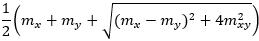
| m1
|
principal bending moment (max)
|
1) The angles of principal magnitudes are derived from to the local axis x.
2)The principal magnitudes can be visualized also as trajectories (see the option Trajectories in the command properties).
|
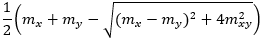
| m2
|
principal bending moment (min)
|
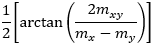
| ab
|
angle of principal bending moment m1
|
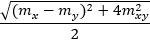
| mtmaxb
|
maximum torsional moment
|
| qmaxb
|
maximum shear force (from bending components)
|
| bb
|
angle of maximum shear force qmaxb
|
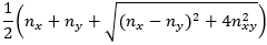
| n1
|
principal axial force (max)
|
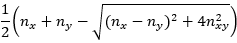
| n2
|
principal axial force (min)
|
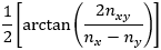
| am
|
angle of principal axial force n1
|
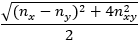
| qmaxm
|
maximum in-plane shear force (from membrane components)
|
Elementary design magnitudes
Resultant
| Type of values |
Values |
Notes |
| Basic magnitudes |
|
mx
bending moment in direction of local axis x
|
| my - bending moment in direction of local axis y |
| mxy - torsional moment |
| vx - shear force perpendicular to plane in direction of local axis x |
| vy - shear force perpendicular to plane in direction of local axis y |
| nx - axial force in direction of local axis x |
| ny - axial force in direction of local axis y |
| nxy - shear force in the plane |
|
1As default, the internal forces refer to the local axes of the individual finite (mesh) elements.
2) The local axes can be displayed by selecting the corresponding option in the View parameters settings.
|
| Principal magnitudes |
|
m1principal bending moment (max)
|
|
m2 - principal bending moment (min)
|
ab - angle between principal bending moment m1 and local axis x
|
mtmaxb - maximum torsional moment
|
|
qmaxb - maximum shear force perpendicular to the plane (from bending components)
|
bb - angle between maximum shear force qmaxb and local axis x
|
n1 - principal axial force (max)
|
n2 - principal axial force (min)
|
am - angle between principal axial force n1 and local axis x
|
qmaxm - maximal shear force in the plane (from membrane components)
|
|
1) The principal magnitudes can be displayed also as trajectories (see the option Trajectories in the command properties). |
| Elementary design magnitudes |
mxD+ - design moment in direction of local axis x on positive surface
|
| myD+ - design moment in direction of local axis y on positive surface |
| |
| |
| |
| |
|
1) The positive surface is considered on the side of positive local axis z while the negative surface is the opposite.
2)The surfaces of the 2D member can be easily swapped by changing the z axis orientation (see parameter Swap in 2D member property list)
|
| Resultant |
|
|
Properties