Buckling factors from stability analysis
SCIA Engineer offers the user to execute a stability analysis which obtains the buckling shape of the structure for a given stability combination. That buckling shape occurs when a certain critical normal force Ncr,i (Euler's critical load) is achieved in the member(s).
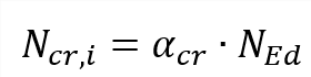
Euler's critical load (Ncr,i) is known after a stability analysis therefore via Euler's formula we can obtain the buckling factor because:
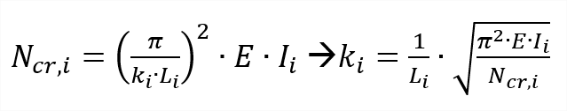
In case of a non-prismatic member, the moment of inertia is taken in the middle of the element.
The buckling factors from stability can only be obtained for the considered span if the average normal force of that span is in compression.
If the average normal force of the given span is in tension then the buckling factors from stability cannot be used. Instead the buckling factors from a linear analysis (see "Calculation buckling ratio – general formula") are used. Also the defined buckling factor limits for that span in tension will be coming from the defined limits in the material setup (not from the defined limits in the stability member data).
Procedure for obtaining buckling factors from stability analysis
Obtaining the buckling factor from stability is the most accurate approach that is available within SCIA Engineer. You can do it as follows:
1) Activate the functionality stability in the project data dialog
2) Create stability combinations
3) Refine the finite element mesh of 1D-members to at least 5 in the mesh settings
4) Define in the solver setup how many eigenvalues (i.e. how many buckling shapes per stability combination) need to be obtained
5) Run the stability combination
6) Determine which stability combination causes buckling in the member by evaluating the 3D-deformations per stability combination.
Two stability combinations need to be obtained for major axis buckling (ky) and minor axis buckling (kz).
Below an example of a stability combination which causes minor axis buckling (kz). This stability combination can be used for obtaining kz.
 buckling")
Below an example of a stability combination which causes major axis buckling (ky). This stability combination can be used for obtaining ky.

7) Create and assign stability member data via the material service (e.g. steel) -> Beams -> Member check data -> Stability member data.
It is important to emphasize that the correct stability combinations are selected for ky and kz (i.e. these should induce major axis and minor axis buckling on this member).

Once defined click on OK and select the target member(s). A label SMD# will appear on these members.
Now you are done. Meaning that the buckling factors on the members with stability member data will be obtained from the stability analysis.
Below you can see a manual verification of the obtained buckling factors from stability.

Buckling factors from linear analysis in case of tension in the buckling span
A member which has stability member data assigned can still use the buckling factors coming from a linear analysis when the average normal force in the buckling span for the given stability combination is in tension.
The user is informed about this via the stability member data in which it is indicated that due to tension in the buckling span that the buckling factors are coming from the linear analysis.
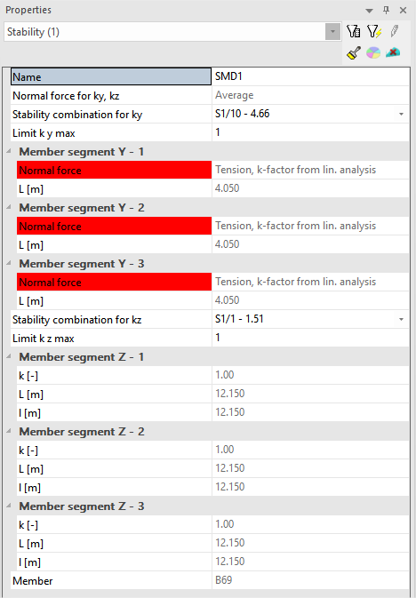
It also means in case of a buckling span in tension that the defined k-factor limits in the stability member data will not be used. Instead the k-factor limits defined in the material setup (e.g. steel setup) are used instead.