Camber design
SCIA Engineer allows the user to automatically determine the camber value in order to counteract the deflection due to total loads uz,max (i.e. to ideally achieve Check uz,max = 1.00).
This is applied on the members if camber definition = Design camber.
Camber design parameters
Before the camber design can be executed the user needs to define some settings in the steel setup or in the buckling group depending where the camber definition is set to "Design camber".

- Minimum camber: The user can input a minimum (absolute) camber value. If the camber design value is lower than this minimum value --> Minimum camber is used.
- Camber limit & Maximum camber: Contains two ways for defining the maximum camber value. If the camber design value is higher than the camber limit value --> Camber limit value is used instead.
- Camber limit = Percent of dead load deflection: The maximum camber value is defined by means of a percentage of the dead load deflections.
- Camber limit = Absolute: The maximum camber value is defined by means of an absolute value. - Round camber to: The obtained camber design value is rounded to the defined increments.
Camber design algorithm
The camber design algorithm works as follows:
1) Verify if Check uz,max > 1.00:
The camber design is only executed on spans which have a unity check that is higher than 1.00 for the deformations due to total loads. Because if the unity check is lower or equal to 1.00 no camber design is needed for the given span as the SLS-check for the total loads (Check uz,max) is already OK.
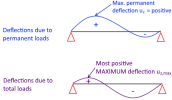
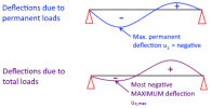
2) Sign determination of max. permanent deflections:
In the next step the sign of the maximum permanent deflection of the given span needs to be obtained. This sign is used for determining which values (positive or negative) of the uz,max deflections need to be obtained and it also directly influences what the sign of the camber will be which will be OPPOSITE.
3) Obtaining max. uz,max with the same sign as the max. permanent deflection:
- Max permanent deflection = positive --> Only positive uz,max values are considered in the given span (def z) from all combinations of the selected envelope combination/class for the camber design --> To be designed camber has a negative sign (opposite to max. permanent deflection sign).
Also the occurring deflections in the camber direction (in this case all negative uz,max values) are taken into account because they can limit the camber design value as we do not want to make the Check uz,max become bigger than 1 for the deflections in the camber directions.
If uz,max only has negative values (i.e. only deflections in camber direction) in this situation--> no camber design because a negative camber would make it worse. - Max permanent deflection = negative --> Only negative uz,max values are considered in the given span (def z) from all combinations of the selected envelope combination/class for the camber design --> To be designed camber has a positive sign (opposite to max. permanent deflection sign)
Also the occurring deflections in the camber direction (in this case all positive uz,max values) are taken into account because they can limit the camber design value as we do not want to make the Check uz,max become bigger than 1 for the deflections in the camber directions.
If uz,max only has positive values (i.e. only deflections in camber direction) in this situation--> no camber design because a positive camber would make it worse.


4) Calculate the needed max. camber design value which gives Check uz,max =< 1.00
- If the span has only one end fixed (cantilever span = Linear camber curve):

- If the span has two ends fixed (simply supported span = Parabolic camber curve):

- If the span has two ends fixed (simply supported span = bilinear camber curve):
- If dx ≤ Ldef,z/2 AND dx1≤ Ldef,z/2:

If dx > Ldef,z/2 AND dx1 > Ldef,z/2:

- If dx ≤ Ldef,z/2 AND dx1> Ldef,z/2:

If dx > Ldef,z/2 AND dx1 ≤ Ldef,z/2:

- If dx ≤ Ldef,z/2 AND dx1≤ Ldef,z/2:
with:
Camber_value_at_free_end: Inputted max. camber value of the span (def z) in case one span ends fixed.
Camber_value_in_the_middle: Inputted max. camber value of the span (def z) in case both span ends fixed.
uz.max.MAX: maximum total deflection uz.max along the span def z (only total deflections in the SAME direction as the max. permanent deflection). See step 3.
uz.max.Camber dir.: maximum total deflection uz.max along the span def z (only total deflections in the OPPOSITE direction as the max. permanent deflection). See step 3.
uz.max.Camber dir. at free end: maximum total deflection uz.max at the free end of the cantilever span def z (only total deflections in the OPPOSITE direction as the max. permanent deflection).
uz.max.Camber dir. at middle: maximum total deflection uz.max at the middle of the span def z with both ends fixed (only total deflections in the OPPOSITE direction as the max. permanent deflection).
uz,max,lowest_UC: maximum total deflection uz,max of the given span def z coming from the combi key with the LOWEST Check uz,max. This value is only used for obtaining the GAP-value in case there is NO deflection in the camber direction.
uz,max,lowest_UC_free_end: maximum total deflection uz,max at the free end position coming from the combi key with the LOWEST Check uz,max. This value is only used for obtaining the GAP-value in case there is NO deflection in the camber direction.
uz,max,lowest_UC_middle: maximum total deflection uz,max at the middle position coming from the combi key with the LOWEST Check uz,max. This value is only used for obtaining the GAP-value in case there is NO deflection in the camber direction.
GAPUz,max,Camber dir.: the gap or spacing between the actual maximum total deflection uz,max along the span def z (only total deflections in the OPPOSITE direction as the max. permanent deflection,= camber direction) and the deflection limit.
- Span fixed at both ends:
In case of deflection (uz,max) in the camber direction:
In case of NO deflection (uz,max) in the camber direction:
- Span fixed at one end (cantilever):
In case of deflection (uz,max) in the camber direction:
In case of NO deflection (uz,max) in the camber direction:
GAPUz,max,Camber dir. at free end: the gap or spacing between the actual maximum total deflection uz,max at the free end of the cantilever span def z (only total deflections in the OPPOSITE direction as the max. permanent deflection,= camber direction) and the deflection limit.
- In case of deflection (uz,max) in the camber direction:

- In case of NO deflection (uz,max) in the camber direction:

GAPUz,max,Camber dir. at middle: the gap or spacing between the actual maximum total deflection uz,max at the middle position of the span def z with both spans fixed (only total deflections in the OPPOSITE direction as the max. permanent deflection,= camber direction) and the deflection limit.
- In case of deflection (uz,max) in the camber direction:

- In case of NO deflection (uz,max) in the camber direction:

Lim.uz.max: deflection limit for total loads for the given span (e.g. 200 defined in the steel setup or in BG)
dx: Section position on 1D-member of uz.max.MAX , starting (0mm) from the begin of the span.
dx1: Section position on 1D-member of uz.max.Camber dir. , starting (0mm) from the begin of the span.
LDefz: System length of the considered span (def z)


5) Apply rounding (=increment) on the calculated camber design value:
The obtained camber value of step 4 is rounded by means of an increment that is defined in the camber design parameter called "Round camber to". This rounding is defined in the buckling dialog or in the steel setup.
The defined rounding in the buckling dialog has a higher priority over the rounding of the steel setup.
Example: If the calculated camber is 12mm and the rounding is set to 5mm --> a value of 15mm is used as the camber value.
6) Verification if the calculated camber design value is higher than the minimum camber:
The obtained camber design value is compared with the defined camber design parameter "Minimum camber".
If the camber design value is lower than the minimum camber --> The minimum camber value is used instead over the calculated camber design value of step 5.
7) Verification if the calculated camber design value is lower than the maximum camber:
The obtained camber design value is compared with the defined camber design parameter "Maximum camber".
If the camber design value is higher than the maximum camber --> The maximum camber value is used instead over the camber design value.
8) Calculate the camber values on every section of the given span:
In this step the camber function can be described on every section position by means of the following formulas:
- If the span has only one end fixed (cantilever span = Linear camber curve):

- If the span has two ends fixed (camber shape = parabolic):

- If the span has two ends fixed (camber shape = bilinear):
- if dx =< Ldef,z/2

- if dx > Ldef,z/2

- if dx =< Ldef,z/2
9) Subtract the camber value of the given section from uz,max:
The uz,max_original deflection (without any camber) needs to be subtracted with the calculated camber values of the corresponding section.
10) Execute the SLS-check with the modified uz,max from the previous step:
The SLS-check is executed based on the modified uz,max.