Drawing manager and drawing rules
The Drawing manager dialogue can be used to select and open Drawing views and to edit their properties.
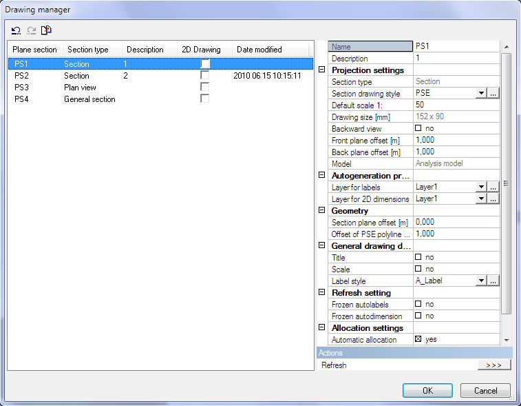
The left side of the dialogue shows a list of PSEs (including some details) available in the model and check boxes for Drawing views. The Date modified item detects when the drawing was refreshed for the last time. The right side of the dialogue shows the properties of the selected PSE. The check boxes select the PSEs that will be opened in Drawing views.
The properties of the PSEs can be changed in this dialogue. The multi select and multi edit options are possible (including “Ctrl + A” to select all).
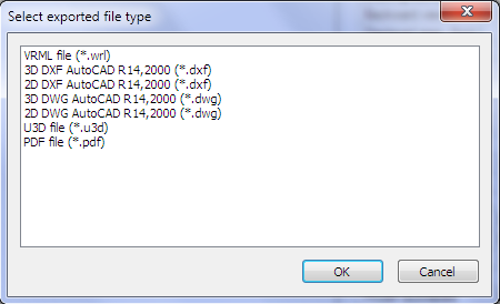
Undo and Redo functions are available to undo or redo the user’s changes in the dialogue. Next the Undo/Redo there is a button for mass export of selected PSEs to various formats – the list is displayed in the picture.
2D drawing generation
Drawing style editor
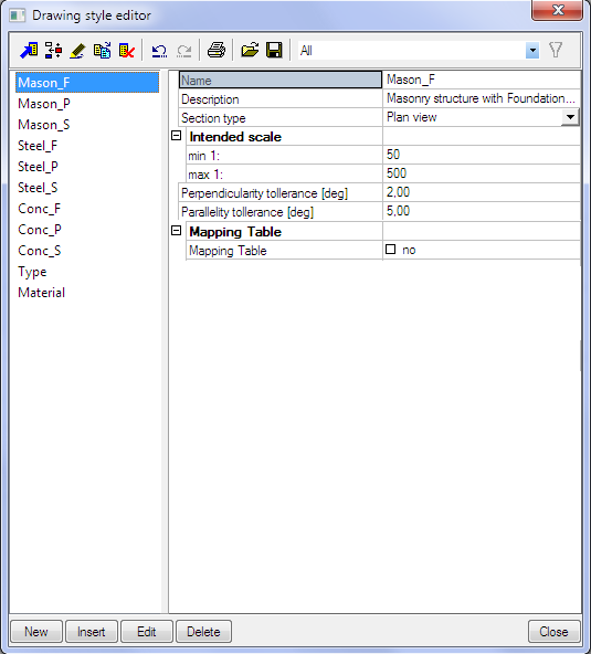
Each PSE has assigned one drawing style – how the projection will be displayed. The existing Drawing styles can be reviewed and edited in the Drawing style editor.
,Drawing styles can be stored / read in DB4 format as other library entities in SCIA Engineer
Each Drawing style has these properties:
- Name: name of Drawing style
- Description: specification of possible use of Drawing style
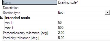
- Section type: Section/Plan view/Both – if a Drawing style is defined only for Section or Plan view – then during creating of a new Section only those Drawing styles are displayed in the properties. Option Both says that the Drawing style can be used for both Sections and Plan views, it is displayed for each type of a new PSE.
- Scale: min - max: informative value for “users” of the drawing style. The range of intended scale is compared to the “Default scale” (property of PSE).
- Perpendicularity tolerance: it is connected with drawing rule “Direction” – tolerance for lines that are to be considered perpendicular to the section plane
- Parallelity tolerance: it is connected with drawing rule “Direction” – tolerance for lines to be considered parallel with the section plane
- Mapping table: see separate chapter
Drawing style
Drawing styles are handled by a standard Library manager. The detailed setup of a drawing style (Concept of drawing rules – see separate chapter) is accessible using the “Edit” function.
Definition of drawing rules
There are two types of rules available: i) rules for lines, hatches and fillings; ii) rules for autolabels.
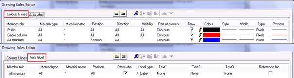
Drawing rules has two different parts, the left side is formed by the definition conditions and the right side is the specification how the structure matching the conditions is to be projected. The left part (condition – red rectangle) is the same for all output devices (screen, document, graphic output), the right side can be different for individual output devices (blue rectangle).
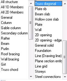
- Member role: the user can select specific structural type (could be different for lines and autolabels)
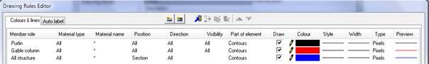
Colours & lines:
Autolabels:
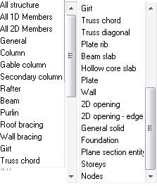
Some types of member role have disabled a part of settings (material, position, etc...).
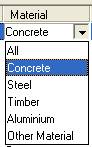
- Material type: the user can select a specific material
- Material name: specification of material by a text string (e.g. C12/15)
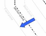
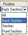
- Position: the user can select the position of the part for which the rule will be applied. Standard view direction is from the Back plane towards the Front plane.
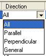
- Direction: the user can select the direction of the line for which the rule will be applied. It is possible to set tolerances for perpendicular and parallel direction in the properties of drawing rule.

- Visibility: this condition specifies whether the rule will apply to visible or hidden or all lines.
The rule for a hidden part of structure can be used only with a rule for a visible part, otherwise it has no meaning.
Drawing style where all Visibility conditions are set to “All” does not need evaluation of hidden lines and is faster that a style where the visibility must be evaluated.
Visibility condition is disabled for Position = “Section”.
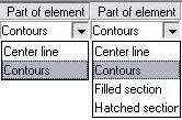
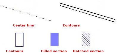
- Part of element: this condition specifies which part of the element will be projected by this rule. There are different Parts of element available for Position = “Section” and different for other positions.
- Draw: controls the drawing of the element, if it is checked then the respective part of the element will be displayed according to the rule. Important is the position of the rule in the list of drawing rules and whether it is checked or not – first rule in the list has the highest priority.

- Colour: specifies the colour of the projection.
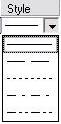
- Style: defines the line type of the projection.
- Width: specifies the line width of the projection.

- Type: selects the type of unit for the line width. If the type is metric then the width will be listed in mm. If the type is in pixels then the width will be listed in pixels.

- Preview: shows the preview of used lines, hatches and styles.
