Displacement loads
Load types available in a particular project may depend on the type of project (2D, 3D, ...) and on the functionality adjusted for the project. The number of available load types is really large.
In this article, we introduce the effect of prescribed displacements for specific points in the structure:
- Point displacement:
- Translation of support
- Translation of a point on beam (relative translation)
- Rotation of support
- Rotation of a point on beam (relative rotation)
- Line displacement:
- on beam - longitudinal strain
- on beam - flexural strain
- 2D member displacement, curvature
Point displacement - Translation of support
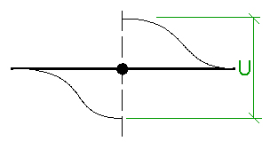
A node of the structure may be subjected to a prescribed displacement. In such a case, you define the direction and magnitude of the known displacement.

Parameters have the following meaning:
- Name: the name is used for the identification of the entity.
- Direction: the direction specifies the direction in which the support 'settles'.
- Reference:
- Absolute: the value (below) is input in absolute value related to the origin of the global coordinate system.
- Relative: the value (below) is input in relative value related to the position of the support.
- Value - U: specifies the value by which the support is translated.
- System: the direction is always defined in the local coordinate system of the support (informative).
The translation of the support can be defined ONLY in fixed supports; it cannot be defined in flexible and non-linear supports.
This example demonstrates the difference between absolute and relative reference.
Let us assume a simple three-span frame with supports as shown in the picture.
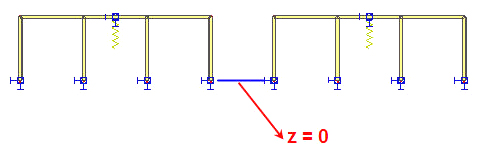
We have two identical frames: the left one for the absolute translation of the support, the right one for the relative translation. The global Z-coordinate of the lower supports is equal to zero, i.e. the supports are located in the global XY-plane.
The translation of a support is assigned to the support located in the middle of the middle-span beam.
The translation in the left frame is input with the following values:

The right variant with the following parameters:

The difference between the absolute and relative reference can be clearly seen in the last picture (the height of the frame is 4 meters).

Point displacement - Translation of a point on beam - rel. translation
A point of the structure may be subjected to a prescribed displacement. The displacement means that the 1D member is 'torn apart' and one part of the 1D member is lifted up while the other part is pushed down. The imposed load is clear from the picture below. The defined magnitude is equal to the distance of 'torn-end-points' of the 1D member.

Point displacement - Rotation of support
A node of the structure may be subjected to a prescribed rotation. In such a case, you define the direction and magnitude of the known rotation.

Note: The rotation of support cannot be defined in flexible and non-linear supports.
Point displacement - Rotation of a point of beam - rel. rotation
A point of the structure may be subjected to a prescribed rotation. The rotation means that the 1D member is 'cracked' and both parts are bent. The imposed load is clear from the picture below. The defined magnitude is equal to the angle between the tangents to the two parts of the 1D member.

Line displacement on beam - longitudinal strain
The whole 1D member may be subject to a longitudinal strain. This strain can be either uniform along the beam or may vary linearly.
Line displacement on beam - flexural strain
The whole 1D member may be subject to a flexural strain. This strain can be either uniform along the 1D member or may vary linearly.

Parameters have the following meaning:
-
Name: is used for the identification of the load.
- Direction: specifies the base direction of the load. The direction may further specified by the Angle item.
- Distribution: the load may be either constant along the 1D member or linearly variable (trapezoidal).
-
Value R: specifies the size of the load.
- System: defines the co-ordinate system in which the load is applied. Only LCS is possible for this type of load.
- Location: specifies whether the load is 'put directly on an inclined 1D member' or whether the 'projection on plan' is defined (only Length option is available here).
2D member displacement, curvature
Parameters:
- Name: defines the name of the load. It may facilitate the identification of the load.
-
Epsilon [mm/m’]: relative elongation due to increase of temperature or shrinkage.
-
k [mrad/m’]: curvature of the plane due to non-uniform increase of temperature or shrinkage.
Considering that the material is homogenous and isotropic and that the temperature is distributed linearly across the member thickness, the elongation of a member due to the increase of temperature can be easily calculated.
Let’s assume increase of temperature at the upper surface TH and increase of temperature at the lower surface TD. The final increase of temperature (shrinkage) can be divided into two components – see the figure below.
Considering this, we obtain:
- elongation (in m/m'):
- curvature:

alpha: coefficient of thermal expansion
Ts: the increased temperature
Positive increase of temperature gives positive value of elongation.

alpha: coefficient of thermal expansion
delta T: difference in temperature between the surface z = -h/2 and z = +h/2.
h: member thickness
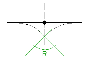
It follows from geometry that k = 1 / R, where R is a radius of a spherical surface the shape of which the members takes if the change of shape due to an increase of temperature is not prevented.
Note: If the increase of temperature is not linear across the member, the distribution of temperature increase must be linearised. The results must be then revised and stress resulting from the difference between the given and linearised increase of temperature must be obtained by a special calculation and added to this result.
Imagine the following – rather theoretical – situation. Let’s have a circular slab supported in its centre only.

First, let’s subject this slab to the uniform elongation of 10 mm/m. It is possible to imagine that both surfaces of the slab are heated.
After calculation, we may see the overall and symmetrical expansion of the slab (the figure shows both the original slab and the deformed finite element mesh).

Second, let’s subject the slab to non-uniform expansion (curvature) of 10 mrad/m. It is possible to imagine that only one surface of the slab is heated.
After calculation, we may see the bowl-like deformation of the slab that results from this type of load. The figure shows the both the original slab and the deformed finite element mesh. The second figure presenting the side-view is more illustrative.