Orthotropic behavior of plates
In engineering practice, you may often come across a situation when the slab (or wall) to be designed has different characteristics (stiffness) in the longitudinal and transverse direction and thus, shows different behaviour in these two directions. Such a behaviour may result from the geometry (e.g. ribbed slabs) or from physical assumptions for a particular situation, for example, when determining deformations in a cracked plate or when excluding vertical members from a horizontal stiffening system (e.g. masonry walls).
Whenever you need to adjust the finite element model accordingly to reflect such a behaviour in SCIA Engineer, the orthotropic properties can be used. These orthotropic properties can be defined in tree ways.
- Orthotropy in the properties of a 2D member:
-
Property modifiers switch on in dialog 'Project data' and tab 'Functionality':
-
Model modifiers switch on in dialog 'Project data' and tab 'Functionality':


Afterwards you can see icons for inputting property modifiers in service 'Structure':
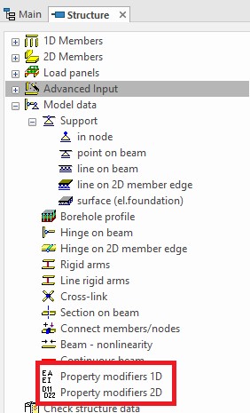

Afterwards you can see icons for inputting Model modifiers in Main tree:

You can input model modifiers for 1D and 2D members and you can assign model modifiers for several Modification groups.
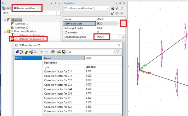
Afterwards you can assign the modification group to a load case.

The difference is in the data you need to enter. In the orthotropy, the stiffnesses are defined directly, while in the property modifier, a factor is specified by which the isotropic stiffnesses are multiplied.
The property modifier is a bit more flexible because it does not depend directly on the properties of the modified part. If you want to enter an uniaxially stretched plate, then you can do that for a 20 cm thick plate and also for a 30 cm thick plate using the same values. The orthotropic properties require that you define separate properties for each of the plates (20 cm and 30 cm one).
On the other hand, also the orthotropy has its advantages. It can be parameterized, and the program includes a set of generators to help you with the input.
However, it is important to explain and understand individual orthotropic parameters (see the recommended reading at the end of the article). The stiffnesses are defined with parameters starting with a 'D' or 'd'.
You can do inputting parameters orthotropy in the following dialog:
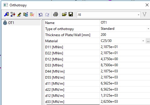
The program can calculate direct the parameters 'D' and 'd' according to the type of orthotropy:

You can do inputting property modifier in the following dialog:

The parameters beginning with 'D' represent plate stiffnesses. The parameters starting with 'd' are membrane stiffnesses.
The direction is derived from the direction of the local coordinate system.
- D11: Flexural stiffness in the 'x' direction (bending)
- D22: Flexural stiffness in the 'y' direction
- D12: Mixed stiffness of D11 and D22 (transverse contraction)
- D33: Torsional stiffness
- D44: Shear flexural stiffness in the 'x' direction
- D55: Shear flexural stiffness in the 'y' direction
- d11: Normal membrane stiffness in the 'x' direction (stretching)
- d22: Normal membrane stiffness in the 'y' direction
- d12: Mixed stiffness of 'd11' and 'd22' (transversal contraction)
- d33: Shear membrane stiffness
.jpg)
In case of a simple, isotropic plate, the stiffness can be expressed using the following formulas:

You can find more information on this topic in SCIA Engineer help:
- Orthotropic properties of slab members
- Library of orthotropy
- Orthotropic slabs: physical and shape orthotropy of plates