Stiffness of the connection between two entities
The stiffness of the connection between two entities is in the first place dependent on the chosen environment in the Project data window.
Tip and trick: The creation of connections as such, regardless of the chosen environment, is discussed in the FAQ ESA1107 How to create a connection between two entities (1D or 2D members)?
- In a Truss XZ and Truss XYZ environment all beams are fully hinged connected to each other and to the supports. It’s not possible to make the connections fixed.
- In all other environments the connection between two entities is regarded by default as infinitely rigid.
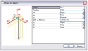
There is nevertheless an option to adapt the stiffness of the connection, namely via the Structure menu > Model data > Hinge on beam. Such a hinge can be added to the beginning and/or end node of a beam.
For the different degrees of freedom (for displacement & rotation) can in each case be chosen between:
- Rigid (infinite stiffness)
- Free (no stiffness)
- Flexible (stiffness value to be filled in by the user)
Keep in mind that in case of flexible stiffness, the stiffness isn’t limited (is infinitive). Stiffness can be limited only by nonlinear behavior and the user has to use nonlinear calculation.
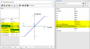
Project data > Functionality > Nonlinearity > Beam local nonlinearity
If Beam local nonlinearity is ticked, the option Nonlinear appears in the properties of Hinge on beam. The user can create the diagram of behavior of the hinge. In this case the stiffness or the rotation of the hinge is limited and user can set the ends of the diagram:
- Free – Bending moment is limited and the rotation is unlimited
- Rigid – Bending moment is unlimited and the rotation is limited
- Flexible – the bending stiffness of the hinge continue according to diagram
The stiffness mentioned in the properties of hinge is used for linear calculation.
STEEL CONNECTIONS
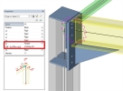
In case a steel connection has been created in a node, an option Update stiffness is available in the properties menu. By selecting this option, the stiffness value of the connection is calculated automatically. When the linear (or nonlinear) calculation is executed again, this stiffness value is taken into account in the analysis model for the distribution of the internal forces.
After the calculation, a hinge is automatically added to the node, so that the user can retrieve the calculated stiffness value.
