Interpolation types for FEM results on 2D members
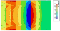
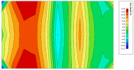
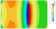
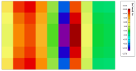
When visualizing results for 2D members, it is possible to see 4 different views on the same result by selecting one of these options for the 'Location' parameter: ‘In nodes – no average’, ‘In nodes – average’, ‘In nodes -average on macro’ or ‘In centres’.
When we run the initial FEM calculation, the solver calculates at first the internal forces in the integration points. An integration point is a point within a finite element at which integrals are evaluated numerically. These points are chosen in such a way that the results for a particular integration scheme are the most accurate.
- In nodes, no average
- In nodes, average
- In nodes, average on macro
- In centres
The calculated values from the previous step are extrapolated from the integration points to the nodes of the 2D finite element using formulas for a hyperbolic paraboloid. These values are now declared the values ‘In nodes – no average’.
This type of results contains raw results. They are normally not used for designing the structure, but they can be used to visually evaluate the mesh size and its influence on the precision of the results. If the mesh elements are too big, then we will notice significant colour jumps between neighbouring finite elements. When this happens, it means that the results are less precise, and that some mesh refinement should be considered in such places.
For every mesh node, a new value is calculated as the arithmetic average of the ‘In nodes – no average’ values from the neighbouring 2D finite elements.
This type of results can be used for a single 2D member but should not be used when your structure contains multiple 2D members or subregions with different thicknesses, because it would lead to incorrect results. As an example, you can imagine a connection between a (horizontal) plate and a (vertical) wall. The results for the nodes on the intersection (between the plate and the wall) will be calculated as an arithmetic average of the results of the plate and the wall – in a general case, these results are not related and might even act in different direction. Therefore, they should not be combined to calculate an average value.
For every finite element node, a new value is calculated as the arithmetic average of the ‘In nodes – no average’ values from the neighbouring 2D finite elements. However, the values from the neighbouring 2D finite elements are averaged only if these finite elements are in the same 2D member, on the same side of an internal edge or subregion and if the node is not defined by the user as an internal node. In these cases, the values are not averaged, and consequently we will see a discontinuity in the distribution of the internal forces.
This type of results is used in most cases. Since we are not averaging past ‘edges’, we do not get wrong results on the edges.
For every finite element, a new value is calculated as the arithmetic average of the ‘In nodes – no average’ values from this finite element. This gives us a mosaic with one averaged value for each finite element.
The advantage of this type of results is that it averages the results over the area of the finite element. If the mesh size is carefully selected, we can easily eliminate (unrealistic) peak results in a 2D member that appear around nodal or linear supports.
One of the disadvantages of averaging towards nodes is that the results in the mesh nodes of the edges of the structure cannot be averaged in the same way as the internal mesh nodes, because there are no values past the edge. Therefore, SCIA Engineer uses another approach along the edges.
The consequent steps of this trick of ‘smoothening the results on edges’ is described in detail in our online help: Smoothening of non-averaged values


