Bolt-rows with 4 bolts
Calculation of resistance of a bolt-row containing 4 bolts is based mainly on the publication: Application of Eurocode 3 to Steel connections with four bolts per horizontal (J.-F. Demonceau, K. Weynand, J.-P. Jaspart and C. Müller) - 2010.
The reference makes a clear distinction between so-called "Outer bolt-row" and "Inner bolt-row" in order to define T-stubs, either vertical or horizontal. Within SCIA Engineer this is related to the classification of bolt-row.

For the Outer bolt-row, the T-stub is vertical, and takes into account two bolts (the T-stub web is the beam flange). The presence of four bolts within this row only influence the values of the effective lengths. The T-stub resistance is calculated by standard formulas for 2 bolt per row. Within Scia Engineer only bolt-row classification "Bolt-row outside of beam " is recognized as "Outer" bolt-row as defined by the reference.
For the Inner bolt-row, the T-stub is horizontal, and takes into account four bolts (the T-stub web is the column/beam/haunch web). The presence of four bolts within this row is taken into account by modification of the effective lengths and by used formulas for T-stub resistance. All Scia Engineer bolt-row classifications except classification "Bolt-row outside of beam "are recognized as "Inner" bolt-rows as defined by the reference.
For further info on the classification of bolt-row see the chapter "Classification of Bolt-rows".
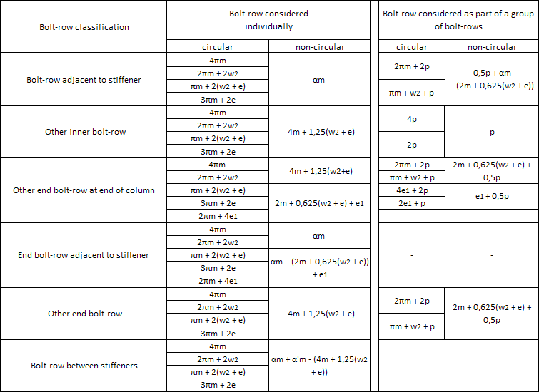
Effective length formulas for column flange classifications used for 4 bolt per row:
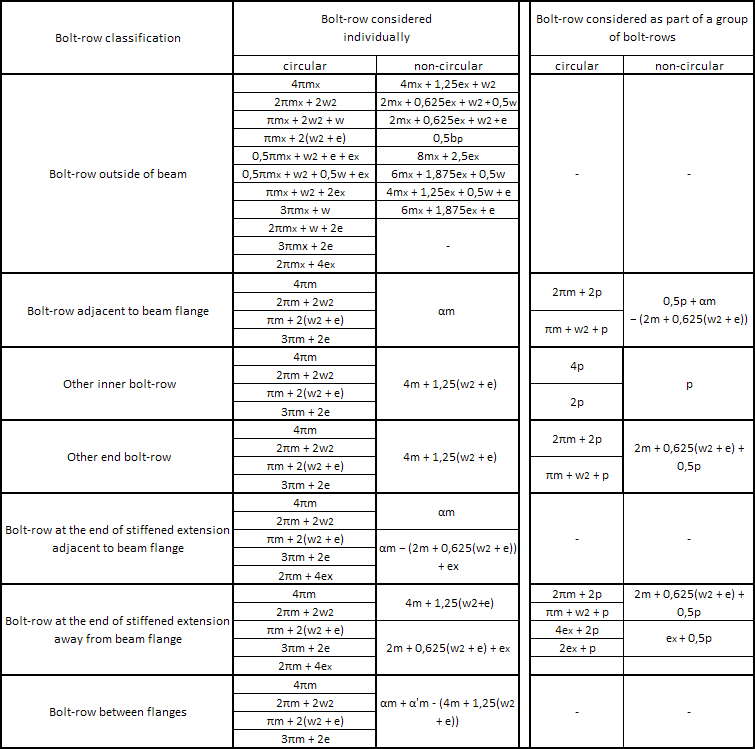
Effective length formulas for end-plate classifications used for 4 bolt per row:
Extract of EN 1993-1-8 Article 6.2.4.1, Table 6.2 - formulas to predict the design resistance of T-stub for 4 bolts per row (only one formula from 4 possible is presented for Mode 1 failure).

The parameters used by the formulas are in general defined by EN 1993-1-8 Article 6.2.4.1, Table 6.2 with the exception that for a T-stub with 4 bolts (bolt row with the blue background in the tables above), n =(w2+e) with n ≤ 1,25*m, n1 = w2 and n2 = e with n2 ≤ 1,25*m+n1.
Conversion of the parameters used in the reference and SCIA Engineer:
|
Bolt-row picture |
FT,Rd formulas |
SCIA Engineer |
|
m1 |
m |
m |
|
e1 |
n1 |
w2 |
|
e2 |
n2 |
e |
Formula for Lb*, for detection of Prying forces, is only valid for 2 bolts per row. In case of 4 bolts per row, no distinction based on presence of Prying forces is needed. Formulas on the right above are always used.
Summary for T-stub resistance for "Inner" bolt-rows:
- Mode 1: All formulas for both Method 1 and 2, including backing plate or not, remain unchanged.
- Mode 2: Modified formulas for "Inner" bolt-row classifications.
- Mode 3: Reduction coefficient 0,9 for "Inner" bolt-row classifications.
In case of 4 bolts per row, coefficient 1.9 is replaced by 3.4 in so-called "Triangular limit" reduction of the tension resistance of bolt-rows given by EN 1993-1-8, Article 6.2.7.2 (9).
The calculation of bolt resistance in shear VRd, takes into account the presence of 2 additional bolts in a bolt-row. The reduction given by EN 1993-1-8 Art 6.2.2 is implemented.
For further info on the calculation of shear force resistance see the chapter "Shear force resistance".