Lateral Torsional Buckling Restraints
LTB restraints are supports against lateral-torsional buckling (LTB) at the top or bottom flange of the beam. The topside is defined by the positive local z- axis of the section. It means that for a positive My (which causes compression at the topside) the LTB length (and the related moment factors) is calculated by the position of the stiffeners at the topside. The bottom side is defined by the negative local z-axis of the section. It means that for a negative moment My (which causes compression at the bottom side) the LTB length (and the related moment factors) is calculated by the position of the stiffeners at the bottom side. When no LTB stiffeners are defined, the values, introduced in the Buckling data dialogue are used.
If required, it is possible to define the position of points where lateral-torsional buckling is prevented.
LTB restraint parameters
Name
Defines the name of restraint.
Position z
Specifies the position in the z-direction, i.e. either the topside or the bottom side.
- For positive moments (the upper flange is in compression), the restraints on the +z side are taken into account
- For negative moments (the lower flange is in compression), the restraints on the -z side are taken into account
Example:
If a steel code check for a beam with the following moment diagram is performed:
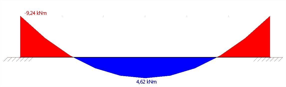
Then, for example, at the position dx = 0, the moment is negative, and therefore only LTB restrains at the -z side (minus "z" side) are taken into account to determine the LTB length for the steel code check;
But in the middle of the beam, the moment is positive, and thus only the LTB restraints at the +z side(plus "z" side) are taken into account to determine the LTB length for the steel code check.
Geometry
Coord. definition
The position can be input in absolute or relative coordinates.
Position x
Defines the position of the restraint.
If more than one restraint is being used, this value specifies the position of the first one.
Repeat
Defines the number of restraint.
This number includes the restraint at the beginning and at the end of the defined interval. If the "on begin" restraint or the "on end" restraint is not included, the actual number of defined restraint is lower (by one or two) than the value defined here.
Regularly
If ON, the restraints are distributed regularly over the length of the beam.
If NOT, the following parameter (Delta x) specifies the distance between the adjacent restraints.
Delta x
This value specifies the distance between the adjacent restraints.
On begin
If ON, the first restraint is defined.
If OFF, the first restraint is not included.
On end
If ON, the last restraint is defined.
If OFF, the last restraint is not included.