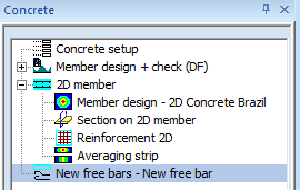
Concrete setup
Input data for calculation can be defined in Concrete setup. Concrete setup is available in tree Concrete.
There are three main groups of properties
Design default
where cover, diameter and direction of reinforcement in two directions for both surfaces will be defined
General
special general parameters for calculation internal forces and design of reinforcement ( reduction coefficient for concrete strut....)
Detailing provisions
parameters and values for calculation detailing provisions are defined
Minimum ratio of reinforcement (only user defined value)
Maximum ratio of reinforcement
Minimum transverse reinforcement
Maximum distance of main reinforcement
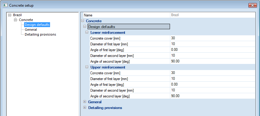
Design default
There are two subgroups in group Design defaults :
- Upper reinforcement
- Lower reinforcement
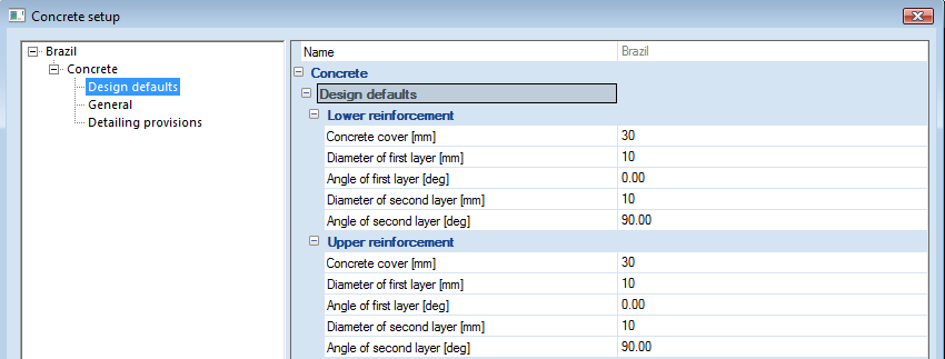
Each subgroups will contain the following properties
Concrete cover
is cover of reinforcement nearer to the surface. In the case of beams and columns the nearer reinforcement is the stirrup rebar. Default value is 30 mm and limit are from 0 to 500 mm
diameter of first layer of longitudinal reinforcement. Default value is 10 mm and limit are from 4 to 100 mm
Angle of first layer
angle between first layer of longitudinal reinforcement and x-axis of LCS of the mesh element of 2D member. Default value is 0 deg with limits from 0 to 180 degree
Diameter of second layer
diameter of second layer of longitudinal reinforcement. Default value is 10 mm and limit are from 4 to 100 mm
Angle of second layer
angle between second layer of longitudinal reinforcement and x-axis of LCS of the mesh element of 2D member. Default value is 0 deg with limits from 0 to 180 degree
General
The following parameters for calculation 2D member were added to existed group General :
Gamma c – partial safety factor of resistances in the ULS (regular combination)
see table 12.1 from NBR 6118. The value is used for calculation of design resistances of concrete in ULS. Default value is 1,4 with limits from 0 to 10.

Gamma s – partial safety factor of resistances in the ULS for reinforcement (regular combination)
see table 12.1 from NBR6118. The value is used for calculation of design resistances of reinforcement in ULS. Default value is 1,15 with limits from 0 to 10.

Theta 1max =1/x – maximum value of inclination
see chapter 11.3.3.4.1 from NBR 6118. This value is expressed as its reciprocal. This value is used for calculation of global imperfection during determination of recalculated internal forces including second order effect. Default value is 200 with limits from 0 to 10 000.
Theta min – minimum angle between compressive diagonals and longitudinal axis
see chapter 17.4.2.3 from NBR 6118. This value is used for determination of shear resistance of concrete. In case minimal angle of compressive strut is exceeded then warning appears to user and theta value is set as minimum
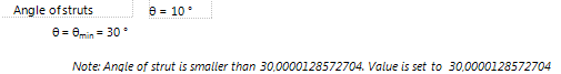
Default value is 30 with limits from 0 to 360 deg.
Theta max – minimum angle between compressive diagonals and longitudinal axis
see chapter 17.4.2.3 from NBR 6118. This value is used for determination of shear resistance of concrete

Default value is 45 with limits from 0 to 360 deg.
Phi – creep coefficient
see chapter A.2.2.3 from NBR 6118. This value is used during recalculation of internal forces including second order effect for compressive members. Default value is 2 with limits from 0 to 100.
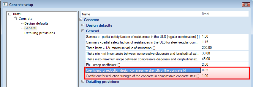
Coefficient for reduction design compressive strength of the concrete
it is coefficient for reduction design compressive strength of the concrete for stress-strain diagram of concrete. Default value is 0.85 with limits from 0 to 1.
Coefficient for reduction strength of the concrete in compressive concrete strut
coefficient for reduction strength of the concrete in compressive concrete strut of 2D member, see chapter 7 Check compression strut. The value is used for check compressive concrete strut in design of reinforcement. Default value is 1.0 with limits from 0 to 1.
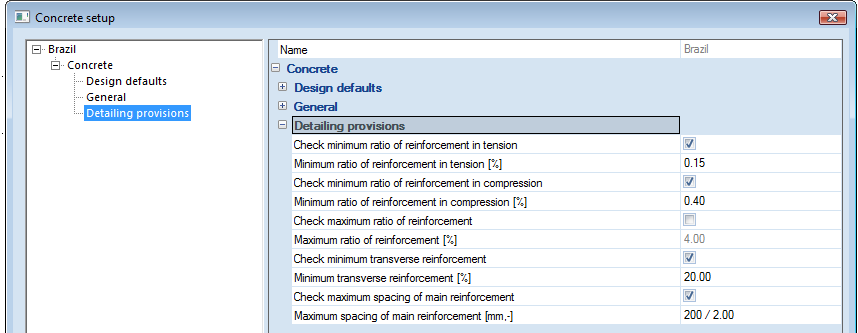
Detailing provisions
There are defined following parameters for design longitudinal reinforcement according to detailing provisions.
Check minimum ratio of reinforcement for beams and slabs
if this check box is ON, then minimum ratio of tensile required reinforcement will be taken into account in design of required reinforcement, see chapter 6.2.1 Check minimum ratio of reinforcement for beams and slabs. Default value is ON.
Minimum ratio of reinforcement for beams
Longitudinal reinforcement or bending : calculated according to chapter 17.3.5.2.1 from NBR 6118/2014.
Transversal reinforcement or shear : calculated according to chapter 17.4.1.1.1 from NBR 6118/2014.
Minimum ratio of reinforcement for slabs
Longitudinal reinforcement or bending : calculated according to chapter 17.3.5.2.1 and Table 19.1 from NBR 6118/2014.
Transversal reinforcement or shear : calculated according to chapter 17.4.1.1.1 from NBR 6118/2014 if necessary.
Check minimum ratio of reinforcement for columns
if this check box is ON, then minimum ratio of compressive required reinforcement will be taken into account in design of required reinforcement, see chapter 6.2.2 Check minimum ratio of reinforcement for columns. Default value is ON.
Minimum ratio of reinforcement for columns
Longitudinal reinforcement or bending : calculated according to chapter 17.3.5.3.1 from NBR 6118/2014. The default value is 0.4%.
Transversal reinforcement or shear : calculated according to chapter 18.4.3 from NBR 6118/2014 if necessary.
Maximum ratio of reinforcement for columns
Longitudinal reinforcement or bending : calculated according to chapter 17.3.5.3.2 from NBR 6118/2014. The default value is 4%.
Check maximum longitudinal reinforcement for columns
if this check box is ON, then maximum ratio of required reinforcement will be taken into account in design of required reinforcement, see chapter 6.2.3 Check maximum ratio of reinforcement for columns. Default value is OFF.
Check minimum transverse reinforcement for columns
if this check box is ON, then minimum transverse reinforcement will be taken into account in design of required reinforcement, see chapter 6.2.4 Check minimum transverse reinforcement for columns. Default value is ON.
Beams longitudinal reinforcement distribution in transversal section
According to chapter 18.3.2.2 from NBR 6118/2014 :
Horizontal direction : 20mm, Ørebar..., 1.2*Øaggreg
Vertical direction : 20mm, Ørebar..., 0.5*Øaggreg
Beams transversal reinforcement distribution in longitudinal section and in transversal section
According to chapter 18.3.3.2 from NBR 6118/2014.
Beams surface reinforcement
According to chapter 18.3.5 from NBR 6118/2014.
Slabs maximum diameter for bending
According to chapter 20.1 from NBR 6118/2014 :
Øbending rebar ≤ hslab/8
Slabs maximum distance between rebars for principal reinforcement
According to chapter 20.1 from NBR 6118/2014 :
eprincipal between rebar ≤ 2*hslab or 20cm
Slabs minimum reinforcement and maximum distance between rebars for secondary reinforcement
According to chapter 20.1 and Table 19.1 from NBR 6118/2014 :
As, secondary ≥ 20%*As, principal or 0.9cm2/m or 0,5*As, minimum
esecondary between rebar ≤ 33cm
Columns longitudinal reinforcement minimum diameter and maximum diameter
According to chapter 18.4.2.1 from NBR 6118/2014 :
Øminimum ≥ 10mm
Ømaximum ≤ (1/8)*MINIMUM(hT ; hL)
Columns transversal distribution for longitudinal reinforcement
According to chapter 18.4.2.2 from NBR 6118/2014 :
ebetween rebar ≥ 20mm, Ørebar..., 1.2*Øaggreg
Columns longitudinal distribution for transversal reinforcement
According to chapter 18.4.3 from NBR 6118/2014 :
ebetween stirrups axes ≤ 200mm, MINIMUM(hT ; hL), 24*Ø for CA-25, 12*Ø for CA-50
Østirrup ≥ Ø/4
emaximum = 90000*(Ø2stirrup/Ø)/fyk
Beams minimum dimensions
According to chapter 13.2.2 from NBR 6118/2014 :
bw, beams ≥ 12cm
bw, deep beams ≥ 15cm
Slabs minimum dimensions
According to chapter 13.2.4.1 from NBR 6118/2014.
Warning : In cases according Table 13.2 from NBR 6118/2014 n factor should be consider in calculation.
Columns minimum dimensions
According to chapter 13.2.3 from NBR 6118/2014.
Warning : In cases according Table 13.1 from NBR 6118/2014 n factor should be consider in calculation.
Check maximum spacing of main reinforcement
if this check box is ON, then maximum spacing of main reinforcement will be taken into account in design of required reinforcement, see chapter 6.2.5 Check maximum spacing of main reinforcement. Default value is ON.
Maximum spacing of main reinforcement
it is maximum spacing of main (major) reinforcement according to NBR 6118,chapter 20.1. The default value is xA = 200 mm and xB = 2∙h ( where h is thickness of the 2D member) and minimum from these value is taken into account. The both direction of reinforcement at surface are major reinforcement for check this detailing provisions.