Type of analysis
The EN 1992-1-1 defines several methods for analysis of second order effects with axial load (general method, simplified method based on nominal stiffness, simplified method based on nominal curvature...). The SCIA Engineer allows making analysis of second order effect by using the following methods:
- General method - equilibrium and resistance is verified in the deformed state, deformations are calculated taking into account the relevant effects of cracking, non-linear material properties and creep, see clause 5.8.2(2) in EN 1992-1-1,
- Simplified method based on nominal curvature according to EN 1992-1-1, clause 5.8.8
General method
General method in SEN is based on physical nonlinear calculation (PNL module) , which can be used only for 1D member. The geometrical nonlinearity and initial deformation can be taken into account too.
The steps for calculation:
- set functionality in project data,
- definition of PNL data,
- definition of nonlinear combination,
- definition of stress-strain diagram of concrete and reinforcement for PNL calculation,
- setting of buckling data,
- setting of nonlinear calculation,
- evaluation of the results.
Second order effects may be ignored if they are less than 10 % of the corresponding first order effects. This condition can be analysed in SCIA Engineer by stability calculation, see separate chapters Setting of buckling data and Member buckling data. It means that if critical load factors for all stability combinations are greater than 10, then the structure is thus not sensitive for second order effects.
Setting of functionality in project data
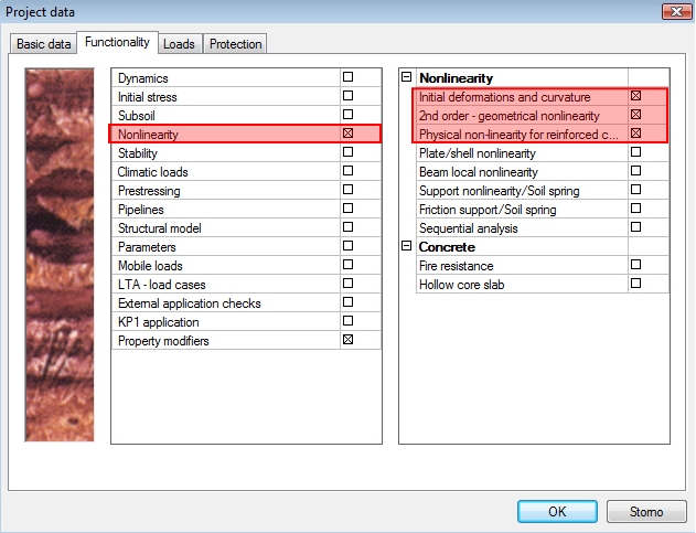
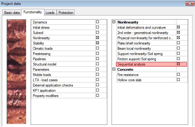
The check box Physical non-linearity for reinforced concrete in dialog Project data > tab-sheet Functionality has to be ON for using PNL module (general method). If we want to take into account geometrical nonlinearity too, the check boxes Initial deformations and curvature and 2nd-order – geometrical nonlinearity have to be ON too.
Definition of PNL data
The special data (attribute) Beam-PNL member data (tree Structure >Model data) has to be defines before physical nonlinear calculation (PNL module).
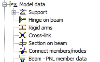
These data has to be defined for each 1D member and the user can define the following properties via these data:
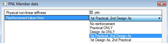
- check box Physical non-linear stiffness – if this check box is ON, the non-linear stiffness with using nonlinear stress-strain diagram will be calculated for member, where PNL data are defined. Otherwise stiffness from linear calculation will be used.
- Combo box Reinforcement taken from - the user can select, which reinforcement will be taken into account.
- No reinforcement – the reinforcement will not be taken into account.
- Practical only – the user real reinforcement (free bars or reinforcement input via REDES ) defined on the member will be taken into account
- Design As only – the required reinforcement designed in the service Member design – design (tree Concrete Advanced > 1D member). It means that required reinforcement has to be designed before non-linear calculation on the member.
- 1st Practical, 2nd Design As – if the user reinforcement is inputted on the member, then user reinforcement will be taken into account. Otherwise, the required reinforcement, if it is calculated, will be taken into account.
- 1st Design, 2nd Practical – if the required reinforcement is designed on the member, then required reinforcement will be taken into account. Otherwise, the user reinforcement, if it is inputted, will be taken into account.
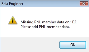
If the PNL data are not defined on all 1D members, the program gives warning on the picture below before running nonlinear calculation
Definition of non-linear combination
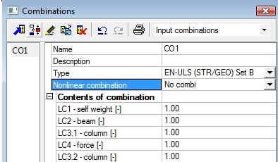
Nonlinear combination has to be defined before physical nonlinear calculation (general method). The nonlinear combination can be created manually or created automatically from linear combination.
- The load coefficient has to be taken into account for definition of nonlinear combination
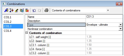
- Nonlinear combination can be created from linear code dependent combination with load coefficient by following procedure:
o Click button New from linear combination in dialog Nonlinear combinations
o Change representation of combination to Contest of combination in dialog Combinations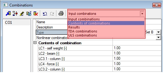
o Select one contest of combination and close the dialog
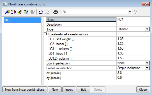
The user can define initial deformation and curvature for each nonlinear combination. According to code EN 1992-1-1, clause 5.2, it is necessary to define geometric imperfections for nonlinear combination too. There are many possibilities for definition of geometric imperfection for nonlinear combination. The detailed description of definition geometrical imperfection is in [5]
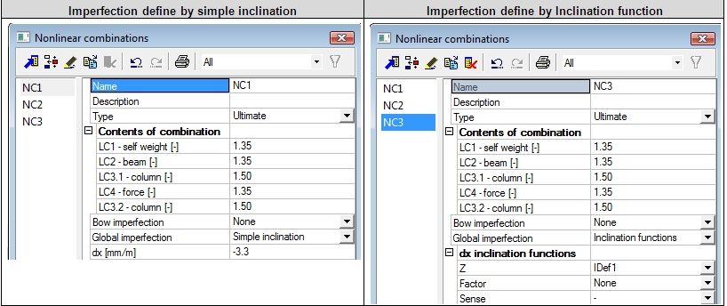
Imperfection define by simple inclination Imperfection define by Inclination function
The value of simple inclination in both direction can be calculated according to code EN 1992-1-1, clause 5.2(5-7) or presented values to in the service internal forces in tree concrete (see chapter Calculation recalculated bending moment for columns) can be used
It is necessary to input more nonlinear combination, with different sense (sign) of inclination, because the imperfection can be applied in the positive or negative direction (according to the chosen global direction).
Definition of stress-strain diagram of material for PNL calculation
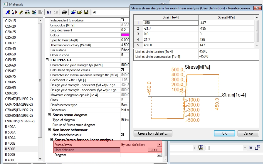
The stress-strain diagram of concrete and reinforcement for nonlinear calculation can be defined in dialog for definition of material in group EN 1992-1-1 > Non-linear behavior.
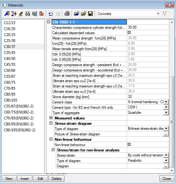
The strain-stress diagram of materials for PNL calculation should be adapted according to EN 1992-1-1, clause 5.8.6 (3).
Concrete material
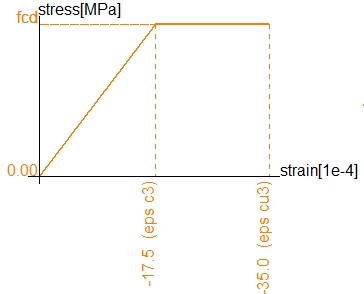
Stress-strain diagram for concrete given in 3.1.5 ( expression 3.14) in EN 1992-1-1 may be used for PNL analysis. With stress-strain diagrams based on design values, a design value of the ultimate load is obtained directly from the analysis. In expression (3.14), and in the k-value:
- fcm has to be substituted by the design compressive strength fcd
- Ecm has to be substituted by Ecd, see expression 5.20
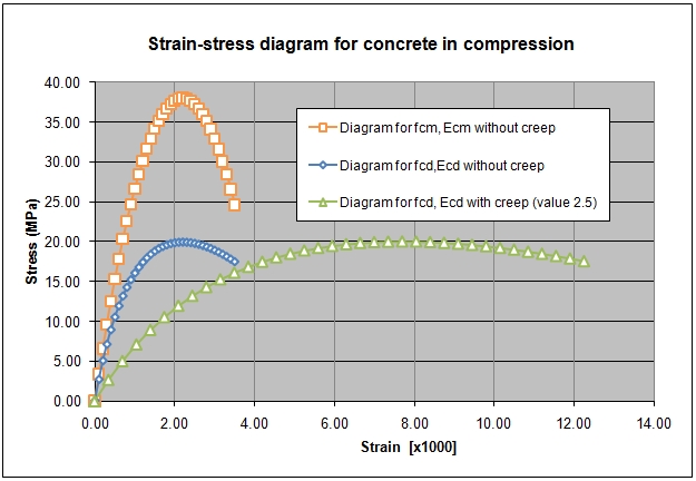
Creep may be taken into account according to according to EN 1992-1-1, clause 5.8.6 (4). It means that strain values in concrete stress-strain diagram can be multiplied by factor 1+fef, where fef is the effective creep ratio according to 5.8.4. The idealised diagram and design stress-strain diagram for concrete C30/37 with and without creep are on picture below
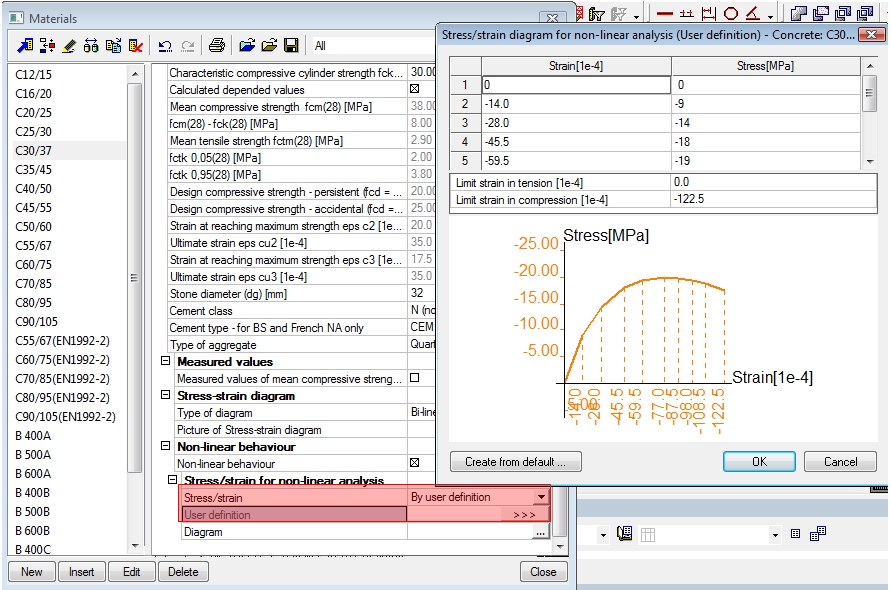
Predefined diagram for nonlinear analysis in SEN are calculated for values fcm and Ecm without influence of creep. For definition of design strain-stress diagram for PNL calculation, it is necessary to correct values in predefined diagram or to define new user diagram (combo box Stress/strain = By user definition) in dialog User definition.
The value creep ratio for calculation effective creep ratio can be calculated according to EN 1992-1-1, annex B.1 or the value can be loaded from concrete member data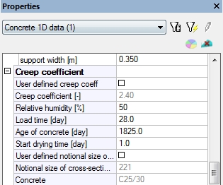
Reinforcement material
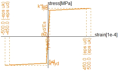
Design stress-strain diagram of reinforced steel given in 3.2.3 (figure 3.8) in EN 1992-1-1 may be used. With stress-strain diagrams based on design values, a design value of the ultimate load is obtained directly from the analysis. Predefined diagram for nonlinear analysis in SCIA Engineer are calculated for values fyk, it means idealised diagram are used. For definition of design strain-stress diagram for PNL calculation, it is necessary to correct values in predefined diagram or define new user diagram (combo box Stress/strain = By user definition) in dialog User definition.
Setting of buckling data
The important parameter for general method is setting of correct values of effective length of the column. There are many possibilities for setting or calculation effective length of the column, see chapter Member buckling data. The second order effect shall be verified in the deformed state of structure according to EN 1992-1-1, clause 5.8.2(2). It follows, that effective length of the column should be calculated after nonlinear calculation too. It is possible to calculate these effective length in SCIA Engineer by using linear stability analysis after a geometric and nonlinear analysis (sequential analysis). The nonlinear process is done in following way;
- Non-linear analysis is performed. If bow or global imperfections are defined, then they are taken into non-linear analysis. Deformed shape and internal forces are calculated.
- Deformed shape and internal forces calculated in step 1 are taken as initial state of the structure for stability analysis.
The following procedure has to be done for setting up a linear stability calculation after a geometric and nonlinear analysis (sequential analysis):
- Set-up the physical nonlinear (PNL) and geometrical (GNL) analysis for a defined nonlinear combination
- Switch ON the functionality Sequential analysis in Project data, tab-sheet Functionality, group Nonlinearity

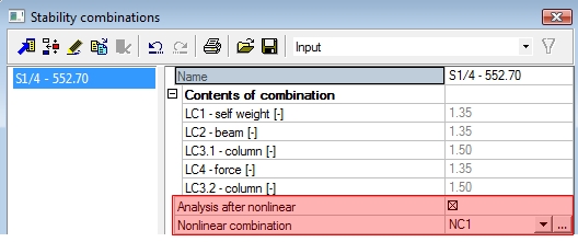
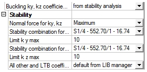
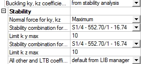
- Define a stability combination which refers to the regarded nonlinear combination from step 1

- Start the linear stability analysis. The required nonlinear analysis is performed automatically which installs the modified initial model for the stability analysis which follows the nonlinear calculation.
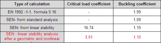
The comparison of calculation buckling coefficient for different method is in the table below. This comparison was made for column of simple frame, see chapter Simplified method.
Setting of nonlinear calculation
Before running nonlinear calculation it is necessary to check and set some parameters of nonlinear calculation in "Solver Setup" .
The detailed information about parameters are here: " Nonlinear calculation"
There are two basic groups for setting of nonlinearity:
• group Nonlinearity for setting parameters for geometrical nonlinearity, where most important parameters are type of geometrical nonlinearity and method of calculation.
- Picard – for small displacements, small rotations and small strains for 2nd order, or for 3rd order
- Newton – Raphson – for 3rd order and large displacements, large rotations and small strains
- Modified Newton – Raphson – for 3rd order and large displacements, large rotations and small strains
More detailed information about these methods is in [5]
• group Physical nonlinearity for setting parameters for physical nonlinearity, where convergence criteria a of number of steps for calculation nonlinear stiffness’s according to input parameters can be set
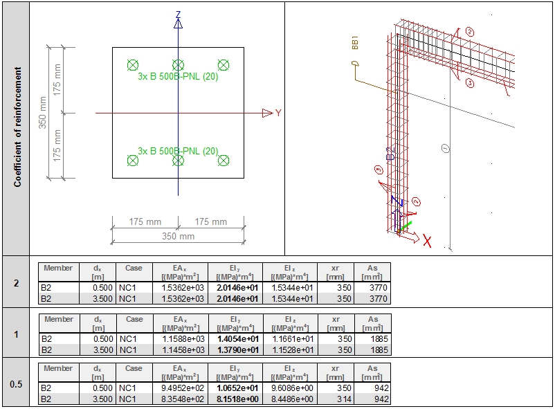
The parameter, which has influence to calculation of nonlinear stiffness, is Coefficient of reinforcement. The required or user reinforcement for all members, which is used for calculation nonlinear stiffness, will be multiplied by this coefficient. It allows quickly to increase or decrease amount of reinforcement for calculation nonlinear stiffness’s, if convergence criteria wouldn’t be reached. There is table of nonlinear stiffness’s of the member with user defined reinforcement for different value of coefficient of reinforcement
Evaluation of the results
The structure after PNL calculation should be checked in services PNL stress/strain and PNL stiffness ( tree Results > Beams ), because only in these nonlinear stiffness (strain-stress diagram for nonlinear analysis) are taken into account.
The bending moment presented in services PNL stress/strain, PNL stiffness and in all services in tree concrete is recalculated to centroid of cross-section with nonlinear stiffness. Only in service Internal forces on beam (tree Results > Beams ) are bending moment recalculated to centroid of concrete cross-section. The value of bending moment presented in service Internal forces on beam can be calculated from bending moment presented in PNL services and in all concrete services according to formula:
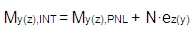
where
My(z),INT bending moment around y(z) axis presented in service recalculated Internal forces on beam
N normal force
My(z),PNL bending moment around y(z) presented in PNL services and in all concrete services
ez(y) The distance (eccentricities) of the centroid of concrete cross-section and centroid of cross-section with nonlinear stiffness presented in numerical output in service PNL stress/strain or PNL stiffness, see chapter PNL stress, strain, stiffness.
The comparison of bending moment My along the member in service Internal forces on beam (tree Results) and in service Internal forces (tree Concrete) and recalculation of bending is in the table below
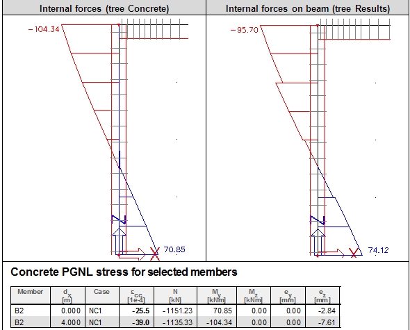
Head of column:
My,PNL= -104,34 kNm; ez = -7,61mm; N= -1135,33 kN;
My,INT = My,PNL + N•ez = -104,34+(-1135,33•(-0,0076))=-95,70 kNm
Foot of column:
My,PNL= 70,85 kNm; ez = -2,81mm; N= -1151,23 kN;
My,INT = My,PNL + N•ez = 70,85+(-1151,23•(-0,0028))=-74,10 kNm
For all checks in tree Concrete are used for check and design the strain-stress diagram defines in group Stress-strain diagram. It means that in these services strain-stress diagram for nonlinear analysis are not taken into account.
If internal forces are calculated with using nonlinear calculation and the services in tree concrete are used, then check box Use buckling data in concrete solver (chapter Buckling data) or in concrete member data ( chapter Group column calculation) has to be OFF, because second order effect would be calculated twice (by general method and by simplified method too)
PNL stress/strain
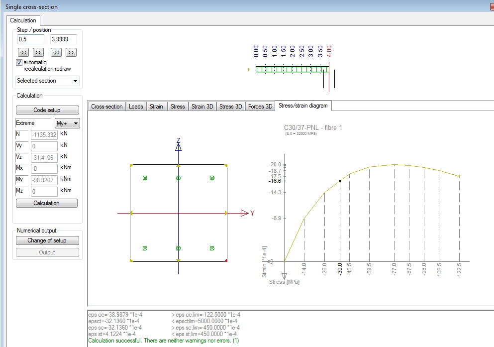
This service allows to evaluate strain and stress in concrete and reinforcement numerically and graphically too.
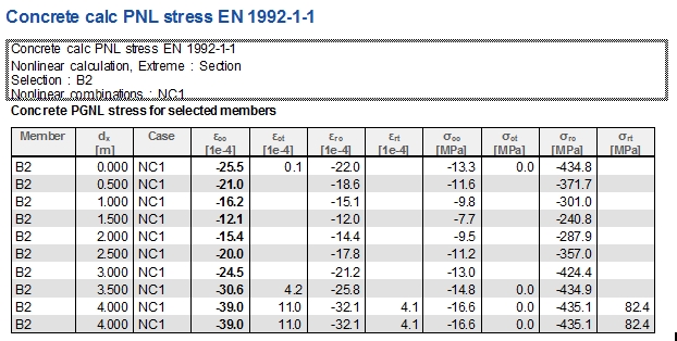
There is possibility to evaluate detailed values via action button Single check
The bending moments presented in this service are recalculated to centroid of cross-section with nonlinear stiffness. The distance (eccentricities) of the centroid of concrete cross-section and centroid of cross-section with nonlinear stiffness is presented in numerical output (values ey and ez)
The values N, My , Mz , ey and ey can be added to the table by selecting these values in dialog Table composer (via icon Table composer in Preview)
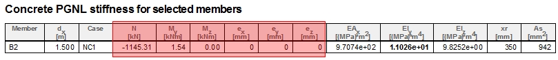
PNL stiffness
This service allows to evaluate nonlinear stiffness numerically and graphically too . The nonlinear stiffness is calculated in centroid of the FEM element and the value is the same at whole length of the FEM element
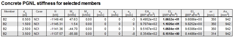
The bending moments presented in this service are recalculated to centroid of cross-section with nonlinear stiffness. The distance (eccentricities) of the centroid of concrete cross-section and centroid of cross-section with nonlinear stiffness’s is presented in numerical output (values ey and ez)

The values N, My , Mz , ey and ey can be added to the table by selecting these values in dialog Table composer (via icon Table composer in Preview)
Simplified method
The simplified method for analysis second order effect should be used after linear calculation. This method in SCIA Engineer is based on nominal curvature according to EN 1992-1-1, clause 5.8.8. The following rules should be fulfilled for using simplified method:
- The internal forces calculated by linear calculation
- The coefficient Use buckling data in concrete solver (chapter Buckling data) or in concrete member data ( chapter Group column calculation) is ON and correct values of buckling data (effective length of the column ) are set (chapter Member buckling data)
The internal forces with second order effect are calculated, if slenderness of the column is greater than limit slenderness (see chapter Check of slenderness). These forces are presented in the service Internal forces (tree concrete), see chapter Check of internal forces. The detailed procedure for calculation second order effect is described in chapter Calculation nominal second order moment.
If internal forces are calculated with using nonlinear calculation and the services in tree concrete are used, then check box Use buckling data in concrete solver (chapter Buckling data) or in concrete member data ( chapter Group column selection) has to be OFF, because second order effect would be calculated twice (by general method and by simplified method too)
There is comparison of general and simplified method in the table for one column of simple frame with two spans (example Tutorial_column_01.esa)
| Model of structure | 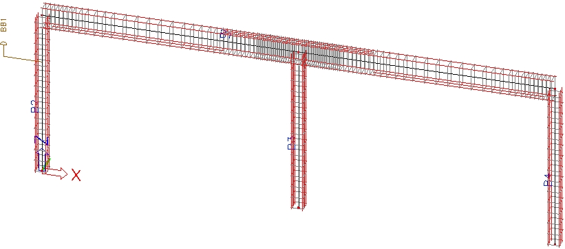 |
|
| Method | ||
| Project setting | 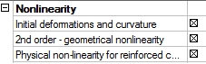
|
All nonlinearity are OFF |
| PNL data | 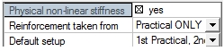
|
No |
| Combination | 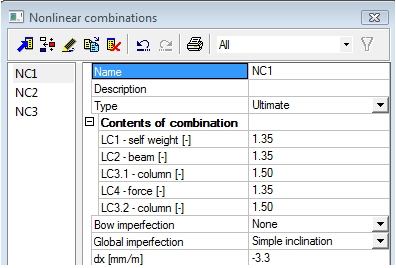
|
|
| Creep | fef = f = 2.5 | fef = f = 2.5 |
| Stress-strain diagram of concrete | 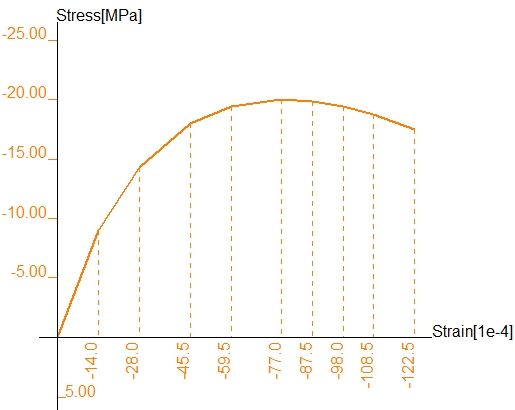
|
|
| Stress-strain diagram of non-prestressed | 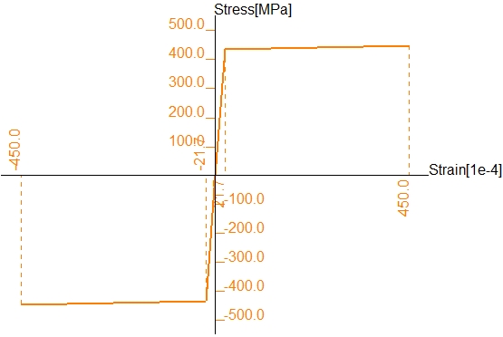
|
|
| Buckling data |
Linear stability ky = 1,15
|
Linear stability ky = 1,15
|
| Internal forces |
Internal forces in tree Results for nonlinear combination NC3
|
Internal forces in tree Results for nonlinear combination NC3 Internal forces in tree Concrete for non-prestrssed ULS check and linear combination C01
|
| Check of column | 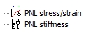
|
All services in tree Concrete
|
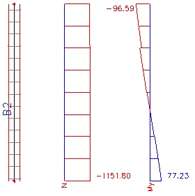
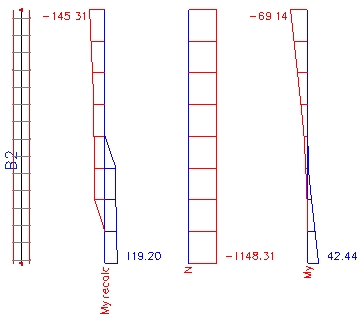

The biggest moment in column B2 without second order effect and imperfection is in head of the column and the value is -69,14 kN/m. For general method, the bending moment in the head with second order effect and imperfection is -96,59, it means 1,39 multiple increasing . For simplified method, the bending moment in the head of column with second order effect and imperfection is -145,31, it means 2,10 multiple increasing . It follows, that using general method lead to more economical design.