Local setting
General
The user can change some parameter from the global setting (parameters with grey background) by creating local setting for selected members. Simply said, where user doesn’t want to use global concrete setting, user creates local concrete setting. We recognize two basic types of these local settings for 1D concrete member:
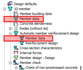
- Member data (Concrete 1D data)
- Member data for automatic member reinforcement design (Concrete autodesign data)
These basic local setting may be created by selecting these two items in tree Concrete Advanced and by selecting of one 1D member, where this data will be defined. The default parameters for new local setting will be loaded from global settings and it is possible to change their.
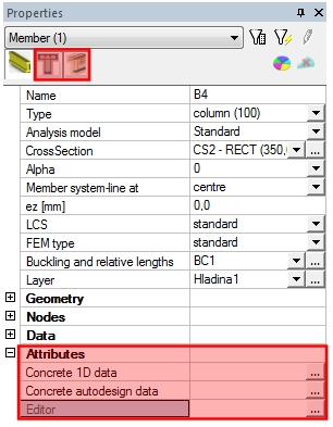
Basic type of local settings were changed since SCIA Engineer 2010 to attributes, what allows to edit parameters of local setting too directly through the properties of selected member.
• For inputting the same local settings for more members is advantageous to input only this setting for one member and then with using geometrical operations to copy or to move this local setting to others members, see chapter Geometrical manipulation with local settings.
• Except of basic types we can define a special local setting for calculation of redistribution for continuous beam (Redistribution data) and local setting for calculation buckling (Member buckling data).Member data (Concrete 1D data)
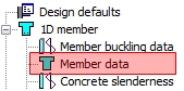
This local setting can be defined via item Member data ( tree Concrete Advanced > 1D member ) and contains default parameters for design reinforcement and check of concrete

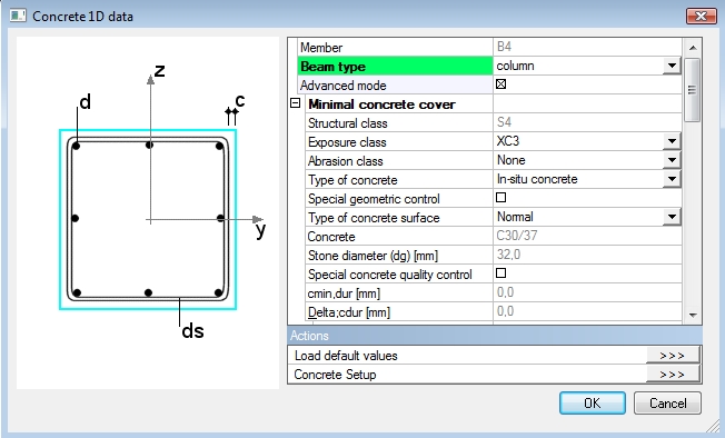
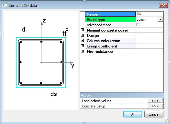
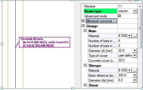
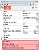
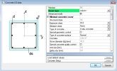
After selection of a 1D member, the dialogue Concrete 1D data is displayed and local settings may be changed and confirmed.
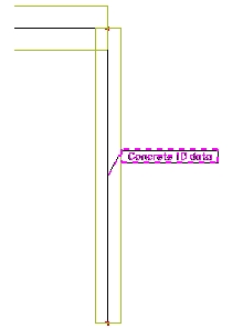
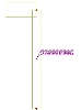
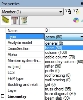
After definition of local setting graphical mark (label) is displayed. After clicking on this mark, user can edit the appropriate attributes in member properties window. Content of the label is also possible to edit through tab-sheet Concrete in dialogue View parameters setting, see chapter Concrete 1D data.
Graphical label Concrete solver setup
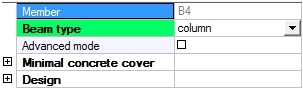
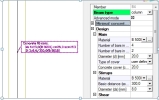
The important parameter in Member data is combo box Beam type, where user can select type of member. There are supported four type of 1D member:
- Beam
- Column
- Slab (beam calculated as slab, it means beam without shear reinforcement)
- Rib (it is active only if rib on the 2D member is defined via item Rib ( tree Structure > 2D member > 2D member components )
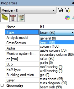
Default value of beam type depends on type defined in member’s properties (value Type). The following default Beam type will be used in member data:
- Column: for Type = column, gable column and secondary column.
- Slab: for Type = beam as slab
- Beam: for other Type
The change of Beam type has influence to design and check reinforcement, because different calculated method is used for column and beam. On the other hand, Beam type has influence to properties, which will be presented in member data too. There are following properties and group of properties for Beam type = Column:
- Advanced mode
- Minimal concrete cover
- Design
- Column calculation
- Creep coefficient
- Fire resistance, if functionality Fire resistance is ON in Project data

Advanced mode
This attribute is a filter for displaying the parameters in member data properties. If it is switched off, then only basic parameters from global settings (Design defaults) are displayed together with reinforcement material parameters. Groups Longitudinal and Minimal concrete cover with the basic parameters are displayed in this case.
Advanced mode = OFF Advanced mode = ON
The properties, which will be appeared in member data for advanced mode, have grey background colour
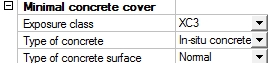
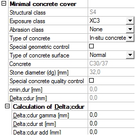
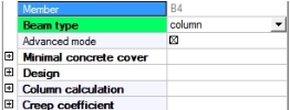
Group Minimal concrete cover
There are parameters which influence to calculation of minimal concrete cover.
Advanced mode = OFF Advanced mode = ON
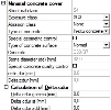
User can edit the following parameters:
- Exposure class (Table 4.1, EN 1992-1-1 )
- Abrasion class (clause 4.4.1.2(13), EN 1992-1-1),
- Type of concrete surface (clause 4.4.1.3(4), EN 1992-1-1)
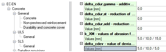
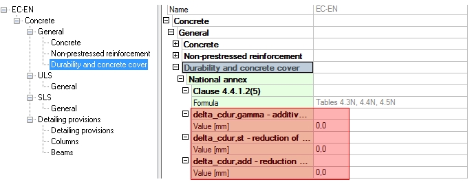
- Special geometric control (clause 4.4.1.3(3), EN 1992-1-1)). The allowance in design for deviation (value Dcdev) is decreased by value defined in concrete setup (Manager for national annex > EN 1992-1-1 > General > Durability and concrete cover >delta_cdev), if the check box is ON
- Special concrete quality control (Table 4.3N, EN 1992-1-1 ). The structural class will be reduced by 1, if the check box is ON
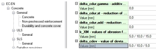
- Values for determination of Delta;cdur (clause 4.4.1.2(6-8), EN 1992-1-1). Default value are loaded from concrete setup (Manager for national annex > EN 1992-1-1 > General > Durability and concrete cover)

The other values are automatically calculated according to input values.
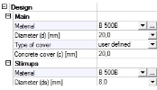
Group Design
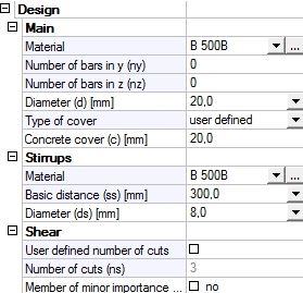
The default parameters for design longitudinal and shear reinforcement are in this group. User can define diameter and material of longitudinal and shear reinforcement.
Advanced mode = OFF Advanced mode = ON
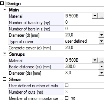
In addition, there are possibilities for definition the additional parameters:
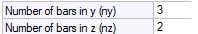
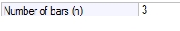
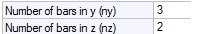
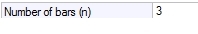
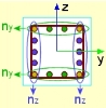
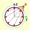
- Number of bars - the user can define user reinforcement directly in concrete member data. This possibility is available:
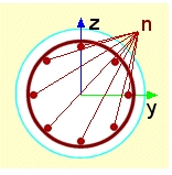
- only for rectangular and circular column and
- if in selected member is not user reinforcement inputted to member via REDES or free bars
Rectangular column Circular column
- Type of cover – there are two options for definition concrete cover:
- Use minimal cover – concrete cover is calculated from inputting parameters defined in group Minimal concrete cover (chapter Group Minimal concrete cover) according to code EN 1992-1-1. The value of calculated value is presented in property Concrete cover, but it is non editable
- User defined – the value of concrete cover is directly input by user via property Concrete cover
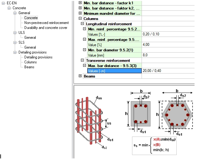
- Basic distance – it is basic spacing of the transverse reinforcement in column. It means, that minimum spacing of transverse reinforcement is calculated as minimum value of this value and of the values defined in detailing provisions in concrete setup (Manager for national annex > EN 1992-1-1 > General > Detailing provisions >Columns >Max.bars distance ). The basic distance will be not taken into account if zero value is set.

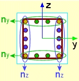
- Number of cuts – number of cuts of transverse reinforcement is calculated automatically according to formula
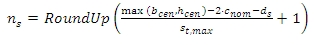
where
bcen width of cross-section in centroid of concrete cross-section
hcen height of cross-section in centroid of concrete cross-section
cnom The nominal value of concrete cover, value presented in property Concrete cover
ds Diameter of transverse reinforcement (stirrup), value defined in property Diameter (ds)
st,max The maximum transverse spacing of the legs, the value is defined in concrete setup (Concrete solver > Detailing provisions >Columns >Transverse reinforcement)
- User defined number of cuts – the automatically calculated number of cuts can be substituted by user value, if this check box is ON. The user value can set to property Number of cuts
The value of concrete cover is related to outer edge of stirrup and for column is the same for all edges of cross-section.
Group Column calculation
The parameters for setting type of calculation for design and check of longitudinal reinforcement can be set in this group. This group is active only, if advanced mode is ON.
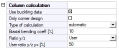
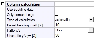
The following properties can be set in this group:
- Use buckling data, see separate chapter
- Only corner design, see separate chapter
- Type of calculation, see separate chapter
- Biaxial bending coeff, see separate chapter
- Ratio y/z, see separate chapter
- User ratio y/z, y= , see separate chapter
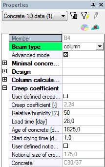
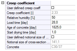
Group Creep coefficient
The parameters for calculation creep coefficient can be set in this group. This group is active only, if Advanced mode is ON.
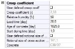
The following properties can be edited by user:
- User defined creep coeff. – if this check box is OFF, then creep coefficient will be calculated according to annex B.1 in EN 1992-1-1. Otherwise, the creep coefficient can be input directly by user via property Creep coefficient.
- Creep coefficient – the value of calculated creep coefficient is presented in this property. This property is active, only if the check box User defined creep is ON
- Relative humidity - relative humidity of the ambient environment
- Load time - is the age of concrete at loading
- Age of concrete - is the age of concrete in days at the moment considered, it means it is age for which the creep coefficient is calculated.
- User defined notional size of cross-section - if this check box is OFF, notional size is calculated according to annex B.1 (formula B.6) in EN 1992-1-1. Otherwise, the notional size can be input directly by user via property Notional size of cross-section.
- Notional size of cross-section – the value of calculated notional size of cross-section is presented in this property. This property is active, only if the check box User defined notional size of cross-section is ON
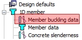
Member buckling data
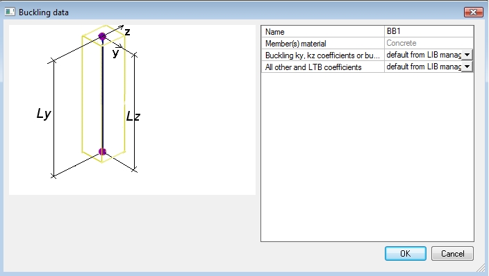
This special local setting can be defined via item Member buckling data ( tree Concrete Advanced > 1D member ) and contains parameters for calculation buckling data.
After selection of a 1D member the dialogue Buckling data is displayed and local settings may be changed and confirmed.
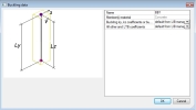
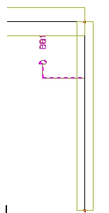
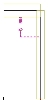
After definition of local setting, graphical mark (label) is displayed. After clicking on this mark user can edit the appropriate parameters in member properties window. This local setting is additional data on the member, it means that this data can be edit only with using graphical marks (label). The graphical mark (label) is possible to switch OFF/ON through the group Member buckling data in tab-sheet Model in dialogue View parameters setting, see separate chapter.
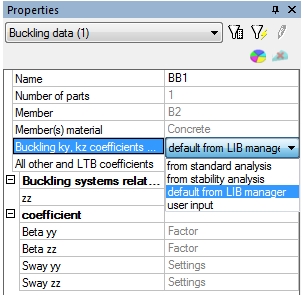
Graphical label Properties window
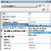
There are following possibilities for calculation effective length or coefficients of effective length (buckling coefficients):
- From standard analysis – approximate formulas described in [4] are used
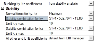
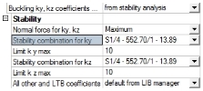
- From stability analysis – this item is active only, if stability combination is defined.
The stability calculation has to be done before definition of coefficients from stability analysis. The user can define:
- which buckling mode (critical load coefficient) will be used for calculation buckling coefficient
- what normal force in member will be taken into account
- limit for buckling coefficients
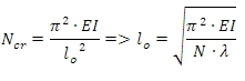
The effective length will be calculated by using Euler’s formula
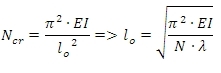
where
EI Bending stiffness of the column around axis, for which the effective length is calculated
N Normal forces at column, which can be determined according to setting in combo box Normal force for ky, kz
l critical load coefficient
lo effective length of the column around axis
The critical load coefficient can be calculated by linear or nonlinear stability calculation and number of critical values can be set in Solver setup. The detailed description of this calculation is in [5].
- default from LIB manager – values for calculation buckling coefficients are loaded from dialogue Buckling and relative length (member properties > Buckling data)
- user input – effective length or coefficients of effective length (buckling coefficients) are directly set in properties of member buckling data.
The detailed description of inputting buckling data and way of calculation buckling data are described in [4]. There is described general functionality, but for concrete member there are additional parameters for definition of buckling data.
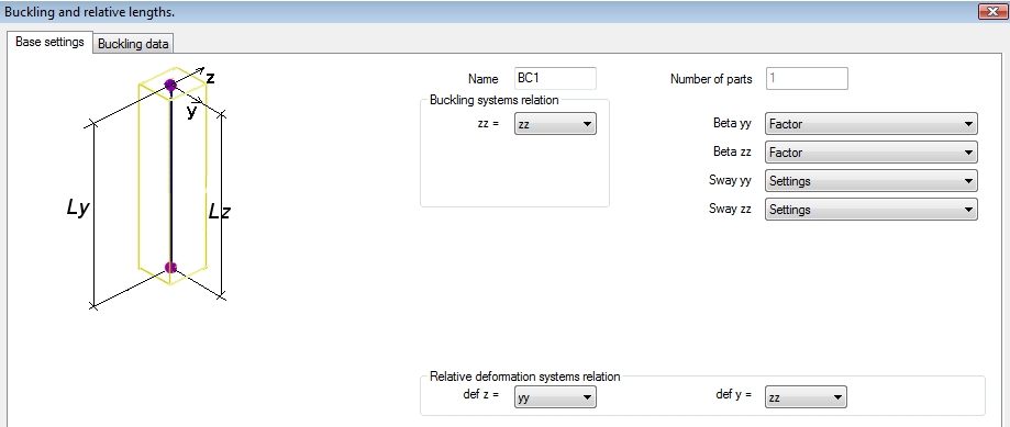
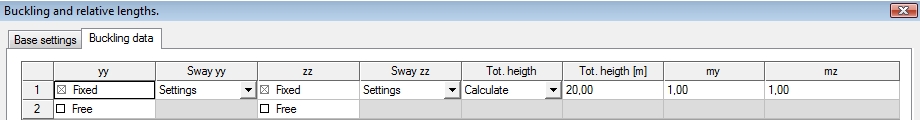
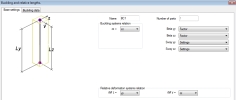
These additional data are important for calculation eccentricities caused by imperfection (see clause 5.2(5) in EN 1992-1-1) and they can be defined in tab-sheet Buckling data in dialogue Buckling and relative lengths (member properties > parameter Buckling and relative length > button Edit ).
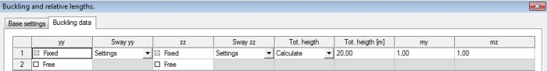
There are following additional data:
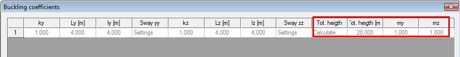
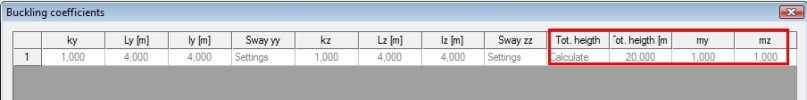
- Combo box Tot. height – this combo allows to set type of calculation of total height of building or length of the isolated columns. There are two items in combo box:
- Calculate – the tot height. will be calculated automatically as sum of lengths of the all members in buckling system
- User – the value can be input directly by the user. The input value will be taken into account if Calculate = User
- edit box Tot. height – this edit box allows to input total height of building or length of the isolated columns directly by the user. The input value will be taken into account if item User is set in combo box Tot. Height.
- edit box my - is the number of vertical members contributing to the total effect of the imperfection perpendicular to y axis of LCS. It means, that value is used for recalculation of bending moment around y axis. Only one value can be set for all columns in buckling system
- edit box mz - is the number of vertical members contributing to the total effect of the imperfection perpendicular to z axis of LCS. It means, that value is used for recalculation of bending moment around z axis. Only one value can be set for all columns in buckling system
The important parameter for calculation of buckling data is type of structure (braced or unbraced). The global type of structure can be set in concrete setup (tree Concrete Advanced > Design default > Design default > Default sway type (for columns and beams only)). For example , the structures is braced perpendicular to y axis of GCS , if check box y-y is OFF (it means the structure is not prone to sway perpendicular to y axis)
Tips & tricks
Graphical mark (label) for local setting
The graphical mark (label) is displayed on the member, if some local settings are defined. Only name of local setting is displayed by default, but this description for some local setting is possible to switch ON/OFF or modify in dialogue View parameters setting, which can be opened:
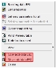
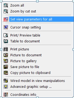
- clicking by right mouse button on graphical window and choosing item Set view parameters for all
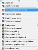
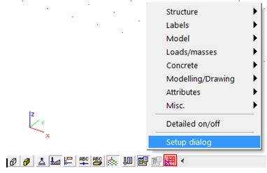
- using an icon Fast adjustment of view parameters on whole model, which is above command prompt and selecting the item Setup dialog
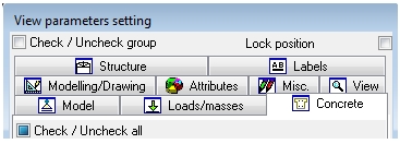
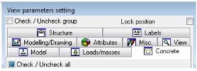
In the dialogue View parameters setting is possible to set view parameters for whole model.
Concrete 1D data
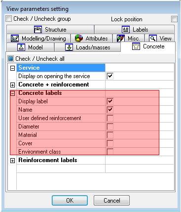
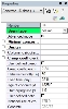
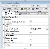
The description in the label for Concrete 1D data can be set in tab-sheet Concrete in group Concrete labels (see picture below).
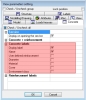
If all parameters in group Concrete labels are switched ON, the description in the graphical label will be following
The graphical mark (label) for Concrete 1D data can be switched ON/OFF by two ways:
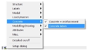
- by check box Display label in group Concrete labels (see picture above)
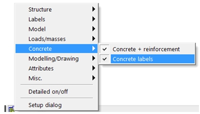
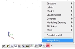
- by check box Concrete label in sub-menu Concrete, which can be opened via icon Fast adjustment of view parameters on whole model (see picture below)
Member buckling data
The description for member buckling data cannot be changed, but the graphical mark (label) for Member buckling data can be switched ON/OFF by two ways:
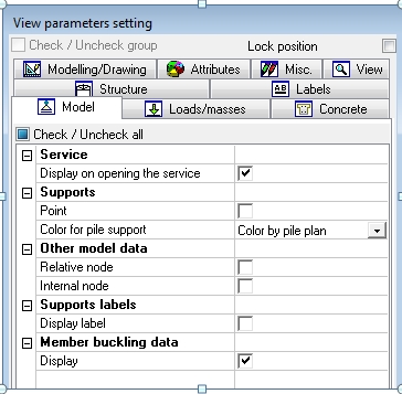
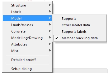
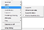
- by check box Display in the group Member buckling data in tab-sheet Model (see picture below)
- by check box Member buckling data in sub-menu Model, which can be opened via icon Fast adjustment of view parameters on whole model (see picture below)
Geometrical manipulation with local settings
The same local settings for more members can be input via geometrical operations for attributes or additional data. At first local setting will input for one member and then by copying this setting will input for others members. Using geometrical operations depends on type of local setting:
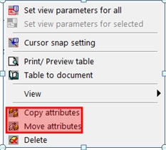
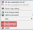
- For local setting defined as attribute (concrete 1D data, concrete autodesign data),... the geometrical manipulation Copy attributes and Move attributes can be used. These functions are available in
- toolbars Geometry manipulations

- menu after selection of attribute and right mouse clicking
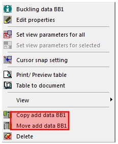
- For local setting defined as additional data (member buckling data) the geometrical manipulation Copy add data and Move add data can be used. These functions are available in
- toolbars Geometry manipulations after selection of additional data

- menu after selection of additional data and right mouse clicking