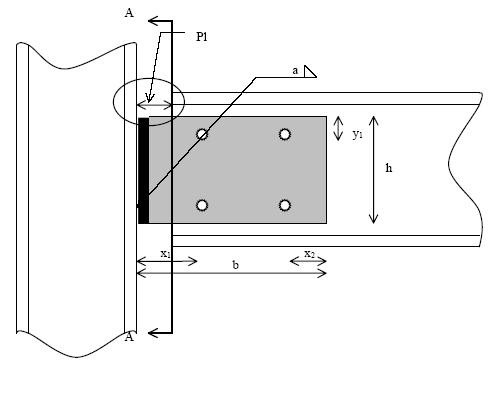
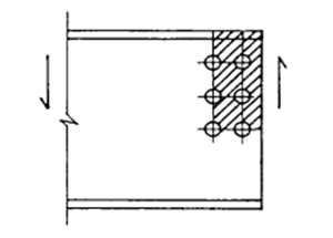
Bolted pinned plate
Calculation design shear resistance VRd for connection element
The design shear resistance VRd is given by

The bolt holes are not taken into account when

When Av.net is less than this limit, an effective shear area of Av= (fu/fy) Av.net may be assumed, else Av=A.
with
|
fy |
the yield strength of the element |
|
γM0 |
the partial safety factor
|
|
A |
h t n |
|
W |
n t h² / 6 |
|
N |
the present normal force |
|
a |
x1 |
|
σN |
the normal stress generated by normal force N |
|
n
|
the number of plates |
|
Av.net |
the reduced shear area
|

Calculation design shear resistance VRd for beam
The design shear resistance VRd is given by :

The bolt holes are not taken into account when

When Av.net is less than this limit, an effective shear area of Av1=(fu/fy) Av.net may be assumed, else Av1=Av.
with
|
fy |
the yield strength of the beam |
|
γM0 |
the partial safety factor |
|
n |
the number of bolt in a section |
|
Av |
the shear area of the beam
|
|
Av.net |
the reduced shear area of the beam element
|
|
fu |
the ultimate tensile strength of the element |


Calculation design shear resistance VRd for bolts in beam
The extreme bolt of the plate is submitted to the following forces (see Ref.[12] IW E1 and Ref. [13] p162-207):
Vertical forces :


Horizontal forces :


The resulting forces acting on this bolt is conditioning by Fv,Rd (See 11.3.1) and Fb,RD,Plate and Beam:

Considering that in the limit state VRd is acting, we get the following equation for VRd. The final VRd is taken as the minimum (in absolute value) of the roots of this equation:

with
|
a |
the position (x direction) of bolt center with regard to underside of the plate |
|
b
|
the position (y direction) of the bolt center with regard to underside of the plate |
|
d
|
the maximum vertical distance between bolts and bolt center |
|
c |
the maximum horizontal distance between bolts and bolt center |
|
e1 |
the end distance |
|
p |
the pitch |
|
Ip |
|
|
n |
the number of bolts |
|
R |
the shear force |
|
N |
the normal force |
|
M
|
the moment: R a |
 : the polar moment of inertia of the bolts with regard to the bolt center
Calculation design block shear resistance for beam element VRd
The design value of effective resistance to block shear is determined by using the following expression given by EN 1993-1-8 Article 3.10.2 (2):
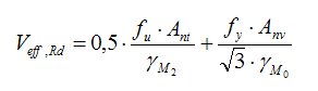
with:
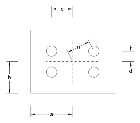
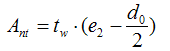
Ant - the net area subjected to tension calculated as:
for a single vertical line of bolts:
for two vertical lines of bolts:
Anv - the net area subjected to shear calculated as:
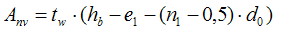
tw - thickness of the beam web
e2 - horizontal distance from the side bolt to the edge of beam
d0 - borehole diameter
p2 - horizontal space between the bolts
hb - height of the beam
e1 - vertical distance from the bottom of the beam to the bolt
n1 - number of bolt-rows
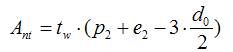
Calculation design block shear resistance VRd in connection element (beam side)
The design value of effective resistance to block shear is determined by using the following expression given by EN 1993-1-8 Article 3.10.2 (2):
with:
Ant - the net area subjected to tension calculated as:
for a single vertical line of bolts:
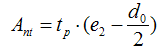
for two vertical lines of bolts:
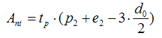
Anv - the net area subjected to shear calculated as:
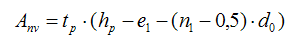
tp - thickness of the element
e2 - horizontal distance from the side bolt to the element edge
d0 - borehole diameter
p2 - horizontal space between the bolts
hp - height of the element
e1 - vertical distance from the bottom of the element to the bolt
n1 - number of bolt-rows
Calculation design compression/tension resistance NRd for connection element
The design compression NRd is given by (see Ref.[2], 5.4.4.(1))

The design tension NRd is given by (see Ref.[2], 5.4.3.(1))

with
|
fy |
the yield strength of the element |
|
fu
|
the ultimate tensile strength of the element |
|
γM0 |
the partial safety factor |
|
A |
the area of the element (n h t) |
|
Anet |
the reduced area of the element |
|
n
|
the number of plates |
Calculation design compression/tension resistance NRd for beam
The design compression resistance NRd is given by (see Ref.[2], 5.4.4.(1))

The design tension NRd is given by (see Ref.[2], 5.4.3.(1))

with
|
fy |
the yield strength of the beam |
|
fu |
the ultimate tensile strength of the beam |
|
γM0 |
the partial safety factor |
|
A |
the area of the beam |
|
Anet |
the reduced area of the beam
|
Calculation design compression resistance NRd for column web
See chapter '"Calculation design compression resistance NRd for column web"'