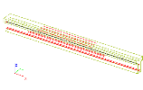
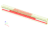
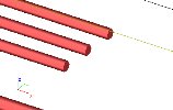
Display style of reinforcement
Display style of shear reinforcement can be controlled via corresponding view parameters from tab Concrete.
Service
|
Display on opening the service |
If ON, the reinforcement is displayed whenever service Concrete or Concrete Advanced is opened. |
Concrete + reinforcement
Concrete labels
|
Display label |
If OFF, none of the following labels is displayed. If ON, the selected labels are displayed. |
|
Name |
Shows the name of reinforcement. |
|
User definedreinforcement |
Shows the basic (user defined) reinforcement (if defined in member data). |
|
Diameter |
Shows the diameter of reinforcement. |
|
Material |
Shows the material of reinforcement. |
|
Cover |
Shows the concrete cover. |
|
Environmental class |
Shows the adjusted environmental class. |
Reinforcement labels
|
Display label |
If OFF, none of the following labels is displayed. If ON, the selected labels are displayed. |
|
Type position number |
The position number is shown (in a circle). |
|
Name |
The name of the reinforcement is shown. |
|
Diameter |
Shows the diameter of reinforcement. |
|
Material |
Shows the material of the reinforcement. |
|
Reinforcement area |
Prints the reinforcement area. |
|
Reinforcement position |
Prints the reinforcement position. |
|
Style of reinforcement position |
Positions on member The x-coordinate of the start- and end-points of the reinforcement is shown. Length of reinforcement Length of reinforcement bars is displayed. Position and length The x-coordinate of the starting point of reinforcement and the reinforcement bar length is displayed |
|
Labels plane |
screen plane The description is put into the screen plane. local beam plane xy The description is put into the selected plane defined by means of local coordinate system of the beam. local beam plane xz ditto local beam plane yz ditto |
|
Stirrup label |
Dimension Dimension line is used to describe stirrups. Symbol Special symbol is used to describe stirrups. |
|
Type position number |
Local Local position numbers for a particular beam are used. The local number is just for a particular member. Global Global position numbers for the whole structure are used. The global number is for the whole structure. |
Read also Display style of reinforcement in slabs.

