Point supports
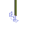
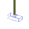
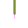
There are three basic types of point supports in SCIA Engineer. Each of them, however, can be of many different configurations.
Standard support
A standard support defines an idealised supporting restricted to a single point. The user may define the way the support acts in individual directions, i.e. in translation along and rotation around axes of selected co-ordinate system.
|
Free |
The support is free in the specified direction. That is it imposes no constraint in the direction. |
|
Rigid |
The support in fully rigid in the specified direction. |
|
Flexible |
The support is flexible (elastic) in the specified direction. The user has to define the required stiffness of the support. |
|
Rigid press only |
Same as pure Rigid but the support acts ONLY under compression. If the support gets under tension it stops acting. |
|
Flexible press only |
Same as pure Flexible but the support acts ONLY under compression. If the support gets under tension it stops acting. |
|
Rigid tension only |
Same as pure Rigid but the support acts ONLY under tension. If the support gets under compression it stops acting. |
|
Flexible tension only |
Same as pure Flexible but the support acts ONLY under tension. If the support gets under compression it stops acting. |
|
Nonlinear |
The stiffness of the support is defined by means of a non-linear function (force-displacement diagram). For more information read chapter Parameters of a non-linear support. |
|
Friction |
The "stiffness" of the support is calculated from defined friction. See chapter Friction support. |
Note: If supports of Press only type (both rigid and flexible) appear in the model, a NONLINEAR calculation MUST be executed. Linear calculation can be run as well, but it does NOT take account of the press only behaviour. The nonlinear calculation requires a definition of a nonlinear load case combination. Unless a nonlinear combination is defined, the nonlinear calculation is not accessible in the calculation dialogue.
Other parameters of a standard support
Note: Parameter Angle mentioned above and the adjustment of orientation described below are available for all support types, not only for the standard support.
Orientation of a support
|
A nodal support may be oriented in: |
|
|
Support on a beam |
A point support on a 1D member may be oriented in:
|
Foundation block
A support may be defined in the form of a foundation block. The supporting is then specified by the material and dimensions of the block together with the properties of the soil below and above the footing surface.
The support of Foundation block type requires the definition of the following parameters.
|
Foundation block |
Selects the type of foundation block. |
|
Foundation |
Defines the properties of the soil below the footing surface. |
|
Upper soil |
Defines the properties of the soil above the footing surface. |
Note: A foundation block can be used only if the Subsoil functionality has been selected in the Project settings and if material Concrete has been specified for the project.
Column
If only a part of the final structure is modelled (e.g. just one or a few floors instead of the whole building), it may happen that a support in the model is in fact a column in the real structure. SCIA Engineer enables the user to model even such situation.
The support is defined through the following parameters. The program automatically calculates the stiffness of the support.
|
Length |
Defines the length of the supporting column. |
|
Hinged |
Says whether the column is pinned at the end or rigidly fixed. |
|
Connection |
The column may either end in the support or may continue (e.g. to another floor). |
|
Cross-section |


